Electro-optical backlighting panel for use in computer-based display systems and portable light projection device for use therewith

a backlighting panel and electronic technology, applied in the field of electronic backlighting panels, can solve the problems of compromising the optical coupling between the backlighting panel and the backlighting panel, rendering it unsuitable for projection viewing mode of operation, and less than commercially attractive,

Inactive Publication Date: 2000-08-15
REVEO
View PDF19 Cites 36 Cited by
  • Summary
  • Abstract
  • Description
  • Claims
  • Application Information

AI Technical Summary

Benefits of technology

During the projection viewing mode, the light reflective surface is not disposed adjacent the second light guiding surface of the light diffusing structure, and light is typically not produced from the light producing means. Rather, light is produced from an external light source and projected through the light guiding panel. Without physically removing the light diffusing structure from the light guiding panel, the state selection means electronically switches the light diffusing structure to its the light non-scattering state of operation. While operated in its light non-scattering state, the light diffusing structure permits the projected light rays to pass freely through the light guiding structure and light diffusing structure, without substantial scattering. Consequently, the projected light rays emerging from the backlighting panel can be used to illuminate optical transparencies, film structures, flat LCD panels and the like, and project images on large viewing surfaces.
When the backlighting panel of the present invention is used to construct a display subsystem having direct and projection viewing modes, switching the backlighting panel from its light diffusive state of operation to its light non-diffusive state of operation is accomplished electronically without having to physically remove or physically modify any component of the backlighting panel. Notably, the novel approach provided by the present invention is in marked contrast with prior art display systems which attempt to achieve the same functionalities by physically removing the backlighting panel from the LCD panel thereof, and consequently suffer from the above-described shortcomings and drawbacks.

Problems solved by technology

However, light can be extracted or leaked out from these surfaces by forming therein scratches, undulations, or any other means of locally altering the critical angle for total internal reflection.
While the prior art backlighting panel design described above has proven useful in the direct viewing of visual imagery on LCD display screens, its permanently formed light extracting pattern renders it unsuitable in projection viewing modes of operation.
While the above-described notebook computer provides both direct and projection viewing modes, it suffers from a number of serious shortcomings and drawbacks which make it less than commercially attractive.
This design requirement necessarily compromises the "optical coupling" between the backlighting panel and the LCD display panel when the system is operated in its direct viewing mode.
From a practical standpoint, the poor optical coupling efficiency in the display panel assembly of the Cruiser computer necessitates higher luminous output from its fluorescent tubes in order to illuminate the display panel to a particular intensity level.
Regrettably, this requirement results in increased power consumption which is highly undesirable in practically all portable computing applications.

Method used


Image

  • Electro-optical backlighting panel for use in computer-based display systems and portable light projection device for use therewith
  • Electro-optical backlighting panel for use in computer-based display systems and portable light projection device for use therewith
  • Electro-optical backlighting panel for use in computer-based display systems and portable light projection device for use therewith

Examples


Embodiment Construction

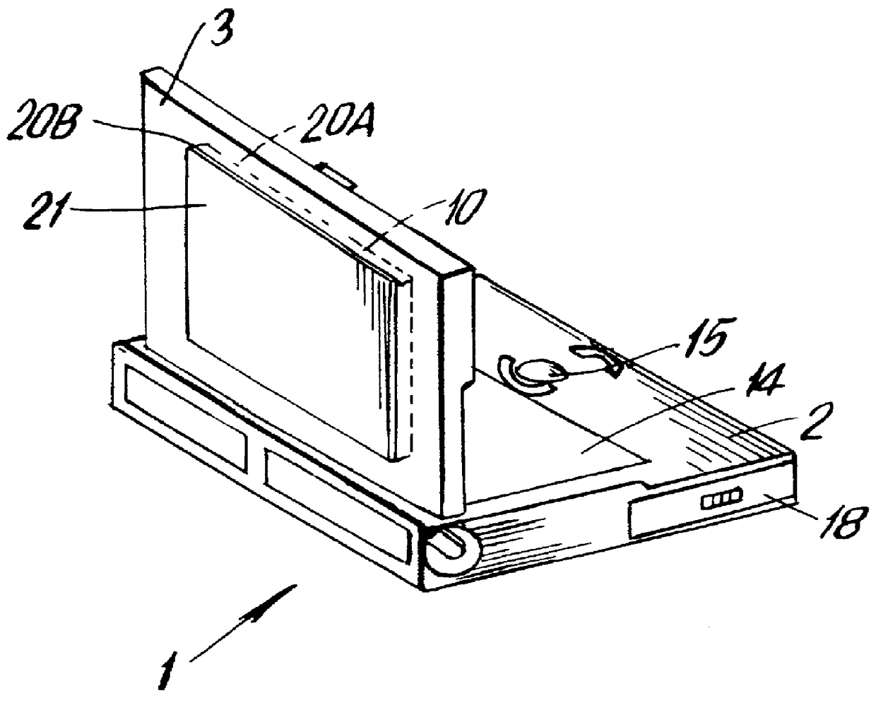
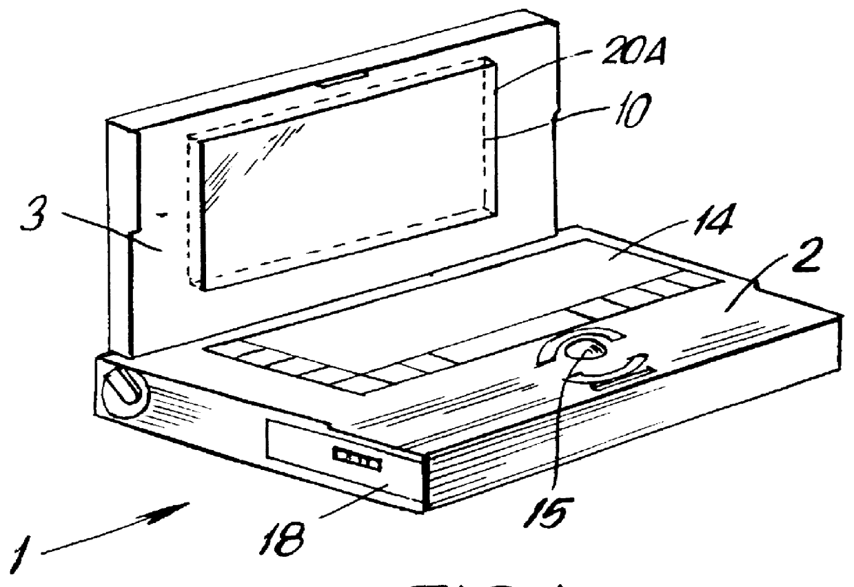
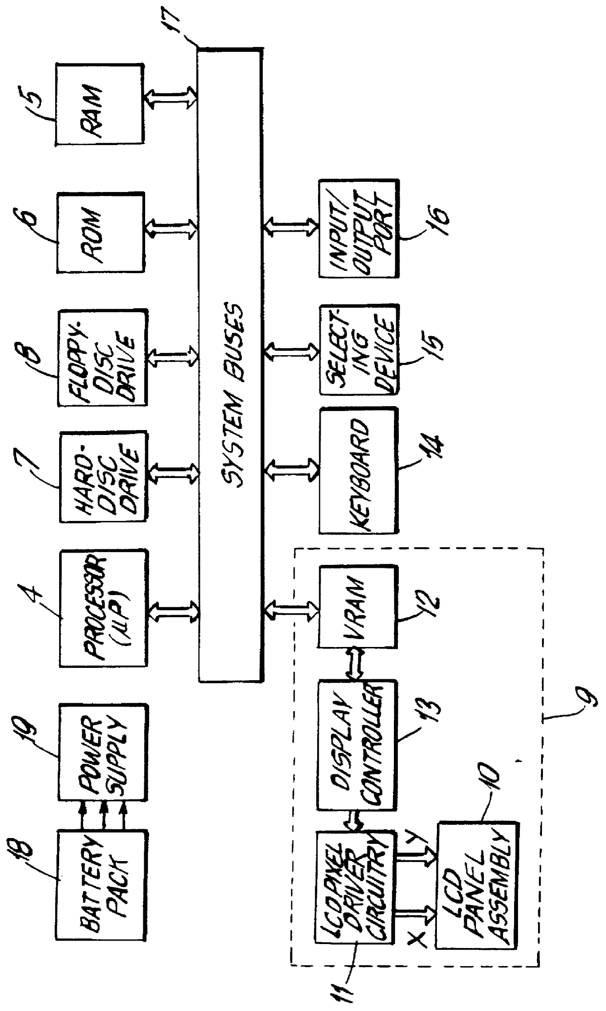
As will be described below, the electro-optical backlighting panel of the present invention can be used in various backlighting environments. For purpose of illustration, the backlighting panel of the present invention is shown incorporated as a component in various portable computer-based systems, namely: the portable notebook / laptop computer illustrated in FIGS. 1 to 5C; the portable notebook / laptop computer illustrated in FIGS. 9 to 11C; the portable image display device illustrated in FIGS. 12 to 12E; and the portable pen-computing device illustrated in FIGS. 13 to 13B. It is understood, however, that the backlighting panel of the present invention may be used with other types of computer-based systems and equipment, including computer monitors, optical transparencies, film structures and the like, without departing from the scope and spirit of the present invention.

In general, the backlighting panel of the present invention comprises an electro-optical structure having a light ...


PUM

PropertyMeasurementUnit
thicknessaaaaaaaaaa
angleaaaaaaaaaa
thicknessaaaaaaaaaa

Abstract

An electro-optical backlighting panel construction for use in portable computer-based systems having direct and projection viewing modes of operation. In the illustrative embodiments of the present invention, the electro-optical backlighting panel is integrated with a LCD display panel, a micropolarization panel, and a touch-screen writing panel to provide several different types of portable computer-based systems including, for example, a portable notebook computer, a computer-driven image display device, and a portable pen-computing device. In general, each of these computer-based systems are capable of selectively displaying color video images on an actively driven display surface, or projecting such video images onto a wall surface or projection screen. These computer-based systems can be easily reconfigured for projection viewing without any sort of physical modification to the LCD display panel assembly. If desired, these computer-based systems can be used to directly view "spatially-multiplexed" images of 3-D objects or imagery during the direct viewing mode, and when desired these spatially-multiplexed images can be projected onto a wall surface or projection screen during the projection viewing mode. When the spatially-multiplexed images are viewed through electrically-passive polarized glasses, the 3-D object is perceived with stereoscopic depth sensation in either mode of viewing.

Description

BACKGROUND OF INVENTION1. Field of InventionThe present invention relates to electro-optical backlighting panels for use in illuminating flat panel displays, optical transparencies, film structures and the like.2. Brief Description of the Prior ArtInclude a flat liquid crystal display(LCD) panel for directly viewing video imagery displayed thereon. Portable computer systems of this type include notebook, laptop, and palmtop computers.In general, prior art LCD display panels have essentially the same basic construction, in that each includes a conventional backlighting structure affixed to the rear surface of either a passive or active matrix LCD panel. Several different backlighting panel designs are described in the technical paper "New Backlighting Technologies for LCDs" by Kevin J. Hathaway, et al., published at pages 751-754 in SID 91 Digest. In recent times, the "light pipe" backlight design, in particular, has been used in many commercially available notebook computers.Specifi...

Claims


Application Information

Patent Timeline
Patent Type & Authority Patents(United States)
IPC IPC(8): G02B27/00G06F1/16G06F3/033H04N13/00H04N5/74G02F1/13G02F1/1334G02F1/1335G02B30/25G02F1/1333G02F1/13357G03B21/132G03B21/30G06F3/00G06F3/01G06F3/041G06F3/048H05B33/12
CPCG02B6/0051G02B27/0093G02B27/26G02F1/1336G03B21/132G03B21/30G06F1/1616G06F1/1626G06F1/1632G06F1/1639G06F1/1645G06F1/1654G06F3/011G06F3/041G06F3/0412G06F3/0414H04N5/7441H04N9/3141H04N13/0037H04N13/0048H04N13/0051H04N13/0055H04N13/0059H04N13/0217H04N13/0239H04N13/0242H04N13/0246H04N13/0275H04N13/0278H04N13/0296H04N13/0422H04N13/0434H04N13/0438H04N13/0454H04N13/0459H04N13/0475H04N13/0477H04N13/0481H04N13/0497H04N19/597G02F1/1334G02F1/133526G02F2001/133538G02F2001/133627H04N5/7491H04N13/0025H04N13/004H04N13/0203H04N13/0257H04N13/0285H04N13/0289H04N13/0425H04N13/0431H04N13/044H04N13/0456H04N13/047H04N13/0484G02B6/0083H04N13/337H04N13/341H04N13/289H04N13/167H04N13/243H04N13/344H04N13/194H04N13/279H04N13/275H04N13/189H04N13/376H04N13/156H04N13/324H04N13/246H04N13/368H04N13/38H04N13/257H04N13/161H04N13/296H04N13/218H04N13/204H04N13/334H04N13/363H04N13/286H04N13/15H04N13/373H04N13/359H04N13/239H04N13/361H04N13/327H04N13/383H04N13/398H04N13/133G02B30/25G06F3/045G02F1/133538G02F1/133627
Inventor FARIS, SADEG M.
Owner REVEO
Why Eureka
Try Eureka