Multi-mode amplifier system

a multi-mode amplifier and amplifier technology, applied in the field of electronic devices, can solve the problems of inefficient linear amplifier operation in these types of signals, general non-linear distortion reduction, and additional challenges, and achieve the effects of facilitating linearization of the amplifier system, reducing out-of-band emissions, and improving amplifier performan

Active Publication Date: 2006-05-09
NORTHROP GRUMMAN SYST CORP
View PDF12 Cites 336 Cited by
  • Summary
  • Abstract
  • Description
  • Claims
  • Application Information

AI Technical Summary

Benefits of technology

[0010]In the envelope tracking mode, a composite input signal component is transmitted to the input terminal of a power amplifier and a variable amplitude supply: signal is transmitted to the supply terminal of the power amplifier. The variable amplitude supply signal is not necessarily an information bearing signal and only needs to maintain a desired headroom over the modulated amplitude of the input signal. In the polar mode, the input signal is converted into two components whose product is proportional to the input signal. A substantially constant envelope, phase modulated component of the input signal is transmitted to the input terminal of the power amplifier, and an amplitude modulated component of the input signal is transmitted to the supply terminal of the power amplifier. In the linear mode, a composite signal component is transmitted to the input terminal and a substantially constant amplitude signal is transmitted to the supply terminal. The combination of these modes can be used to optimize amplifier size / cost, efficiency, signal distortion, and / or OOB emissions.
[0012]In yet another aspect of the present invention, the input signal can be modified via predistortion techniques to facilitate linearization of the amplifier system and to mitigate out-of-band emissions. Separate predistortion is applied to the amplifier input terminal signals and amplifier supply terminal signals. Alternatively, the output signal can be modified by a digital cross-cancellation technique that employs a clean reference signal to compute and correct distortion in the output signal. The digital cross-cancellation technique allows for modification of the input signal to improve amplifier performance that can be corrected at the output of the power amplifier. The predistortion technique and digital cross-cancellation technique can be combined to facilitate linearization and to mitigate out-of-band emissions of the amplifier system.

Problems solved by technology

However, they are generally not operated at high efficiency due to the need to provide high linearity.
Time varying envelopes present an additional challenge.
Thus, there is customarily an inherent tradeoff between linearity and efficiency in amplifier designs.
Therefore, the operation of the linear amplifiers in these types of signals is very inefficient, since the amplifiers need to have their supply voltage sized to handle the large peak voltages even though the signals are much smaller a substantial portion of the time.
Additionally, the size and cost of the power amplifier is generally proportional to the required peak output power of the amplifier.
The cost of the amplifier scales with its, peak power.
Several other circuit costs including heat sinks and DC-DC power supplies scale inversely to peak power and dissipated heat (which results from the electrical inefficiency).
Related base station costs of AC-DC power supplies, back-up batteries, cooling, and circuit breakers also scale inversely with efficiency as does the electrical operating costs.
Clearly, improving DC-RF efficiency is a major cost saver both for manufacture and operation.
This requires much larger, more costly amplifiers to provide the necessary back-off and thus lower efficiency.
Additionally, if the signal varies over a large dynamic range it may cause the envelope tracking amplifier to operate with very low drain voltages resulting in additional signal distortion and eventually causes the amplifier system to shutoff.

Method used


Image

  • Multi-mode amplifier system
  • Multi-mode amplifier system
  • Multi-mode amplifier system

Examples


Embodiment Construction

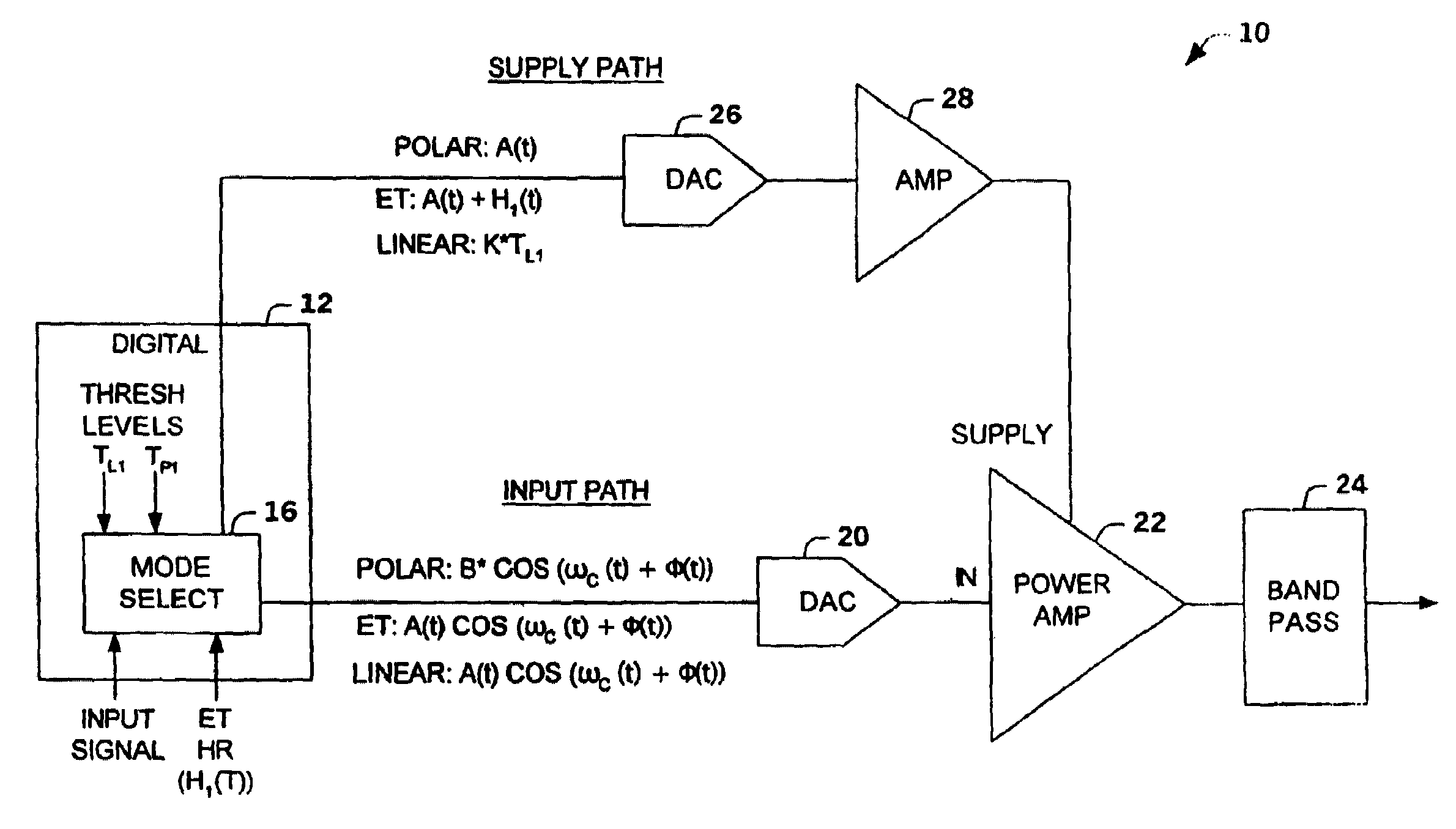
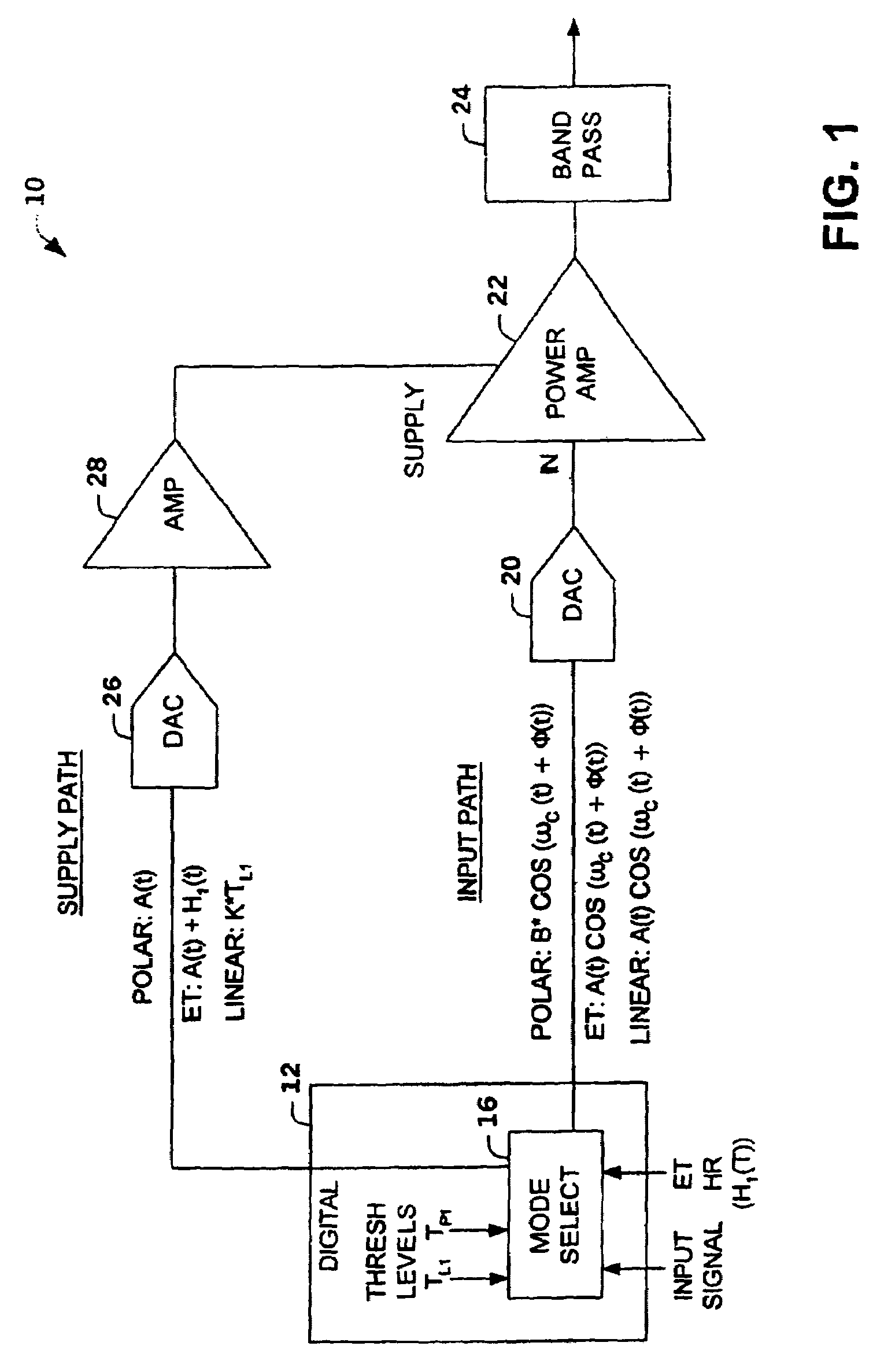
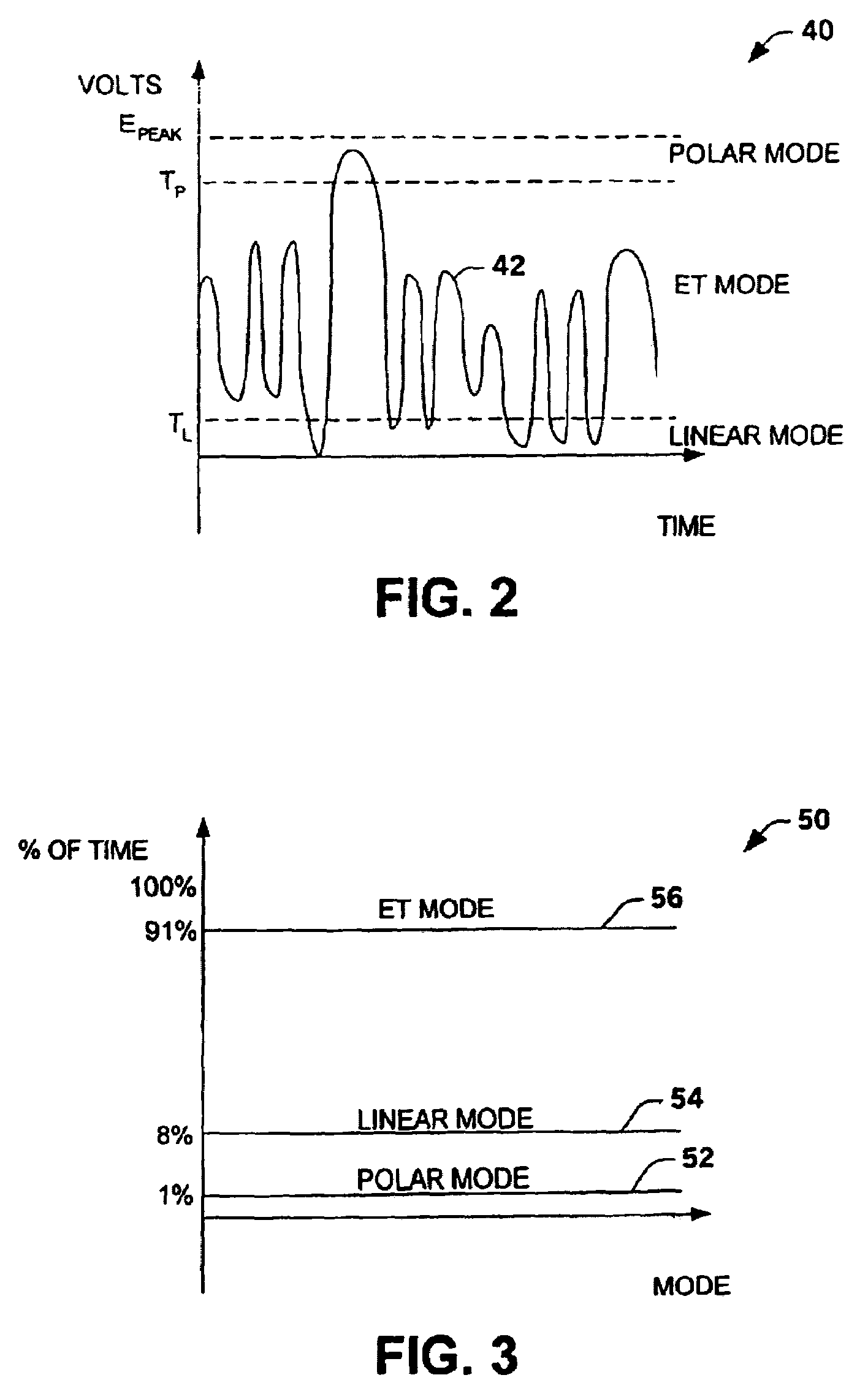
[0022]The present invention relates to an amplifier system that switches between operation in a linear mode, an envelope tracking mode and a polar mode. The amplifier system switches between operations based on a characteristic of an input signal relative to a first threshold level and a second threshold level (e.g., envelope amplitude levels, digital count representation of signal levels, power amplifier power levels). The amplifier system can employ a power amplifier that maintains a constant class configuration. However, a power amplifier that maintains a constant class configuration is not required.

[0023]In one aspect of the invention, the amplifier system operates as an envelope tracking amplifier for signals (e.g., input signals, amplifier output signals) between low amplitude levels and highest amplitude levels. The amplifier system operates as a linear amplifier system (e.g., Class A, A / B, or B,) for low amplitude level signals and as a polar amplifier for peak amplitude lev...


PUM


Abstract

An amplifier system is provided that switches between a linear mode of operation, an envelope tracking mode of operation and a polar mode of operation. The amplifier system switches between modes of operation based upon a characteristic of an input signal relative to a first threshold level and a second threshold level. A mode selector selects the operation mode by transmitting an amplitude modulated signal plus a variable headroom voltage to a supply terminal of a power amplifier during the envelope tracking mode, an amplitude modulated signal to the supply terminal and phase modulated input signal during the polar mode and a substantially constant amplitude signal to the supply terminal during the linear mode.

Description

TECHNICAL FIELD[0001]The present invention relates generally to electronic devices, and more particularly to a multi-mode amplifier system.BACKGROUND OF THE INVENTION[0002]RF power amplifiers used for wireless communication transmitters, with spectrally efficient modulation formats, require high linearity to preserve modulation accuracy and to limit spectral regrowth. Typically, a linear amplifier, Class-A type, Class-AB type or Class-B is employed to faithfully reproduce inputs signals and to limit the amplifier output within a strict emissions mask. Linear amplifiers are capable of electrical (DC power in to RF power out or DC-RF) efficiencies greater than 50% when operated at saturation. However, they are generally not operated at high efficiency due to the need to provide high linearity. For constant envelope waveforms, linear amplifiers are often operated below saturation to provide for operation in their linear regime. Time varying envelopes present an additional challenge. Th...

Claims


Application Information

Patent Timeline
Patent Type & Authority Patents(United States)
IPC IPC(8): H03F3/38H03F3/24H03F1/02H03F1/32
CPCH03F1/0222H03F1/3241H03F1/025H03F2200/331
Inventor ROBINSON, IANWINTER, FRANK
Owner NORTHROP GRUMMAN SYST CORP
Why Eureka
Try Eureka