LED lighting system with a multiple mode current control dimming strategy

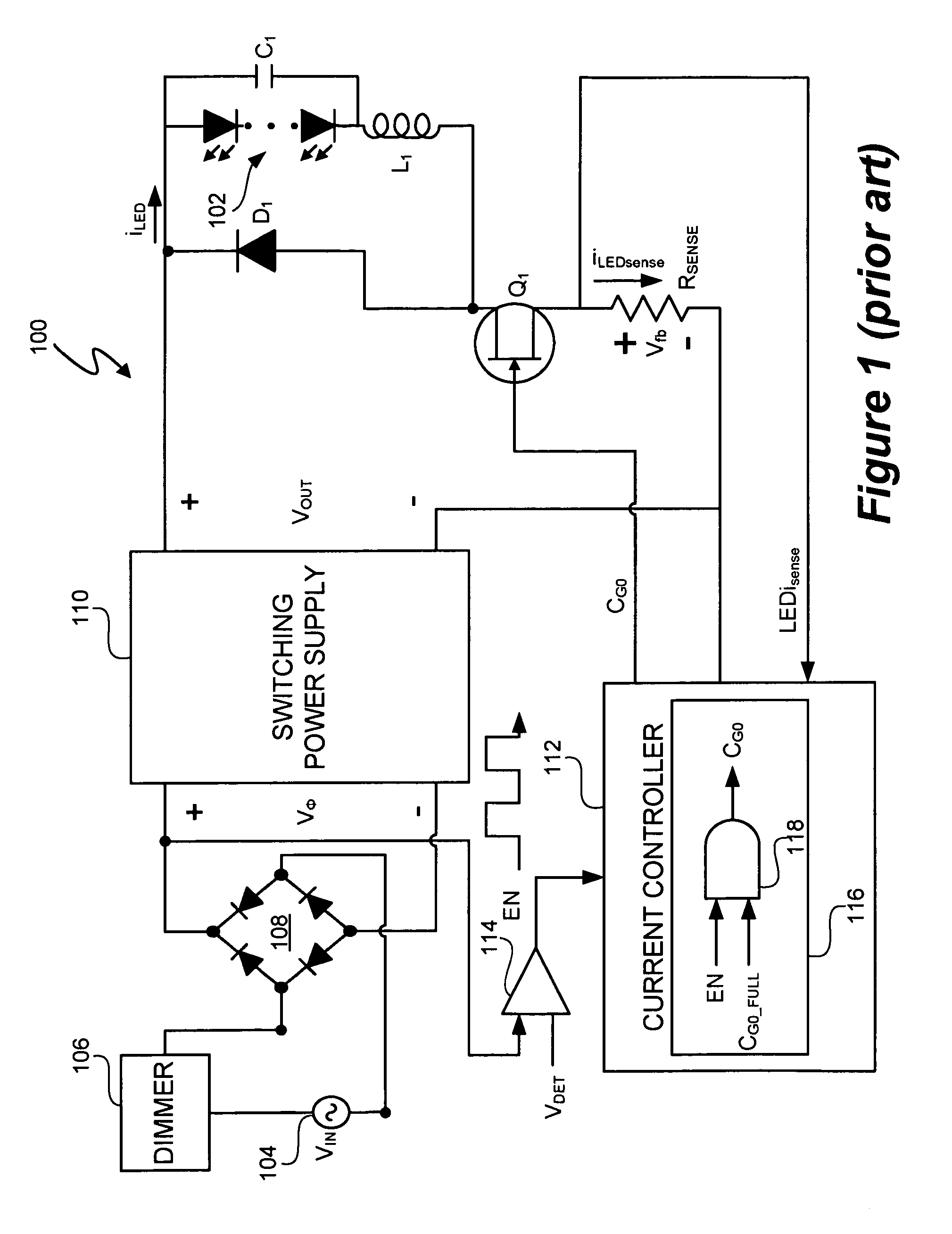
a technology of dimming strategy and led lighting system, which is applied in the field of electronic and lighting, can solve the problems of less efficient operation of led lighting system b>100/b>

Active Publication Date: 2010-07-20
SIGNIFY HLDG BV
View PDF153 Cites 374 Cited by
  • Summary
  • Abstract
  • Description
  • Claims
  • Application Information

AI Technical Summary

Benefits of technology

[0029]In one embodiment of the present invention, a light emitting diode (LED) lighting system includes a controller to control current in an LED. The controller includes components to respond to a dimming level input to control an active v

Problems solved by technology

Furthermore, generally, LED lighting system 100 operates less effici

Method used


Image

  • LED lighting system with a multiple mode current control dimming strategy
  • LED lighting system with a multiple mode current control dimming strategy
  • LED lighting system with a multiple mode current control dimming strategy

Examples


Embodiment Construction

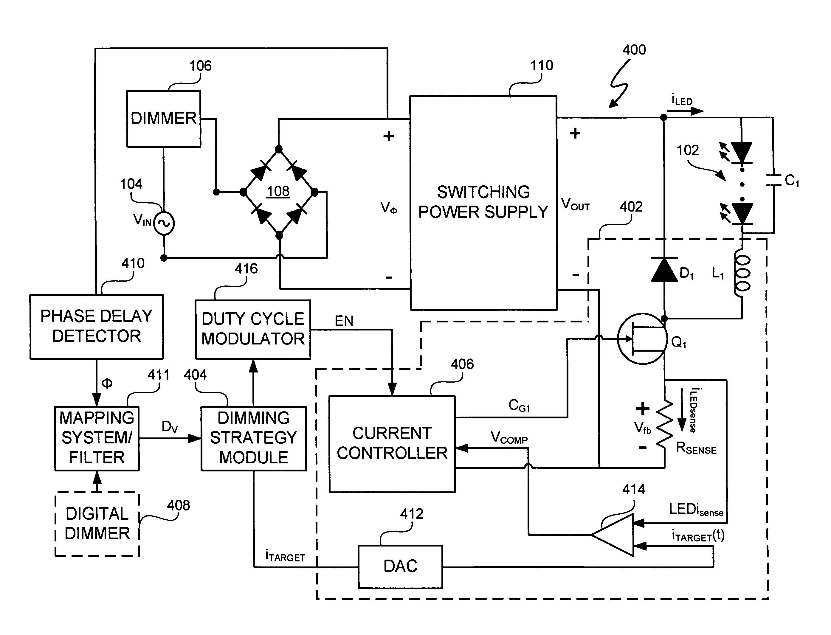
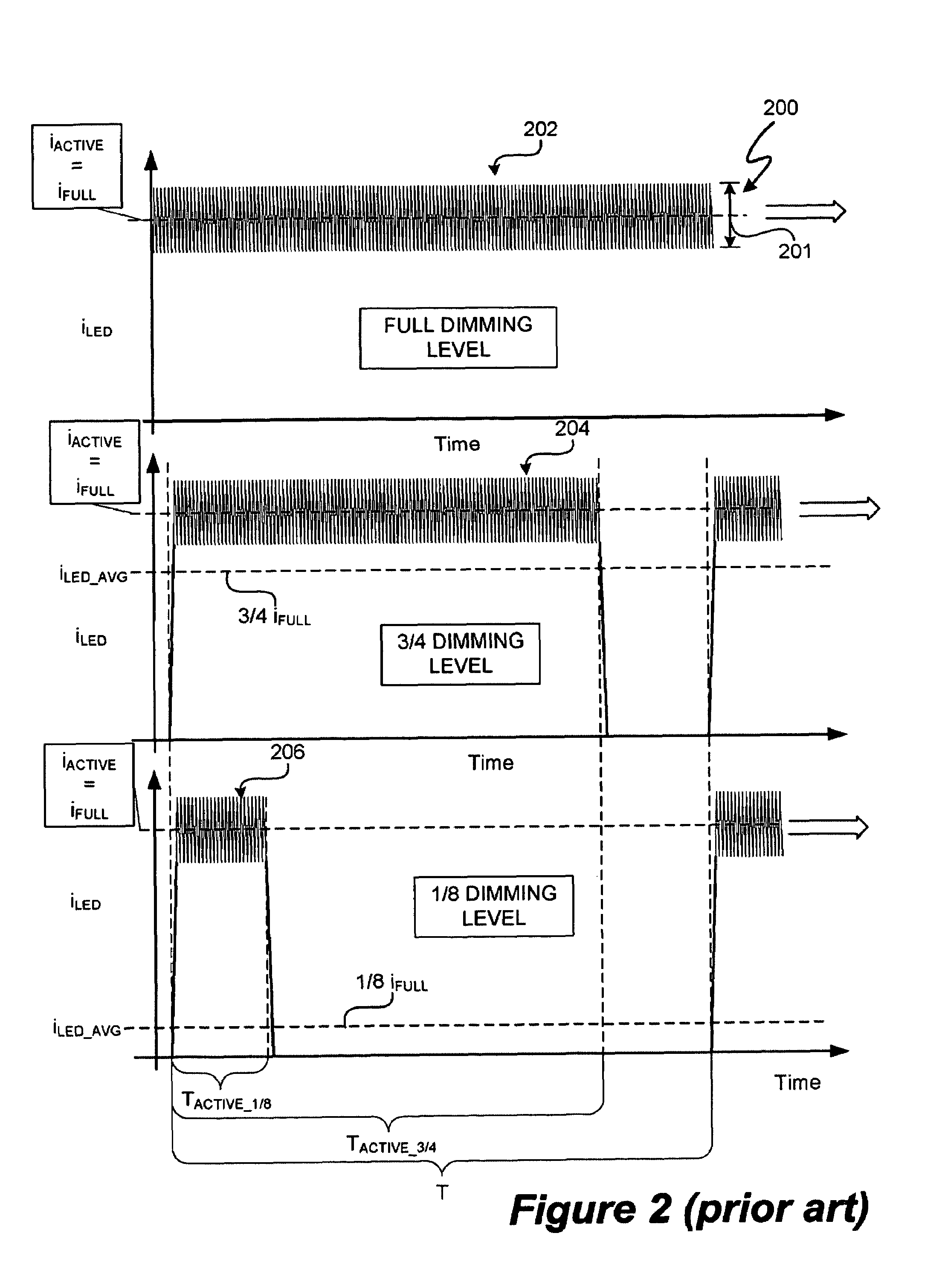
[0043]A light emitting diode (LED) lighting system includes a controller to control current in one or more LEDs in response to a dimming level input. The LED lighting system implements a dimming strategy having two modes of operation that allow the LED lighting system to dim the LEDs using an active value of an LED current less than a full value of the LED current while maintaining continuous conduction mode operation. In an active value varying mode of operation, the controller varies an active value of the LED current for a first set of dimming levels. In an active value, duty cycle modulation mode of operation, the controller duty cycle modulates an active value of the LED current for a second set of dimming levels. In at least one embodiment, the active value of the LED current varies from a full active value to an intermediate active value as dimming levels decrease.

[0044]In at least one embodiment, upon reaching the intermediate active value, the controller modulates a duty cy...


PUM


Abstract

A light emitting diode (LED) lighting system includes a controller to control current in one or more LEDs in response to a dimming level input. The LED lighting system implements a dimming strategy having two modes of operation that allow the LED lighting system to dim the LEDs using an active value of an LED current less than a full value LED current while maintaining continuous conduction mode operation. In an active value varying mode of operation, the controller varies an active value of the LED current for a first set of dimming levels. In an active value, duty cycle modulation mode of operation, the controller duty cycle modulates an active value of the LED current for a second set of dimming levels. In at least one embodiment, the active value of the LED current varies from a full active value to an intermediate active value as dimming levels decrease.

Description

CROSS REFERENCE TO RELATED APPLICATIONS[0001]U.S. Provisional Application No. 60 / 909,458, entitled “Ballast for Light Emitting Diode Light Sources,” inventor John L. Melanson, and filed on Apr. 1, 2007 describes exemplary methods and systems and is incorporated by reference in its entirety. Referred to herein as “Melanson I”.[0002]U.S. patent application Ser. No. 12 / 047,249, entitled “Ballast for Light Emitting Diode Light Sources,” inventor John L. Melanson, and filed on Mar. 12, 2008 describes exemplary methods and systems and is incorporated by reference in its entirety. Referred to herein as “Melanson II”.[0003]U.S. patent application Ser. No. 12 / 047,269, entitled “Lighting System with Power Factor Correction Control Data Determined from a Phase Modulated Signal,” inventor John L. Melanson, and filed on Mar. 12, 2008 describes exemplary methods and systems and is incorporated by reference in its entirety. Referred to herein as “Melanson III”.[0004]U.S. patent application Ser. No...

Claims


Application Information

Patent Timeline
IPC IPC(8): H05B37/02
CPCH05B33/0815H05B33/0848Y02B20/347H05B45/14Y02B20/30H05B45/3725
Inventor MELANSON, JOHN L.
Owner SIGNIFY HLDG BV
Why Eureka
Try Eureka