Screw less clip mounted computer drive

a computer drive and screw less technology, applied in the direction of instruments, furniture parts, electrical apparatus casings/cabinets/drawers, etc., can solve the problems of requiring significant amounts of labor, requiring the use of micro sized machine screws to attach the rails to the computer drives, and not eliminating the use of micro sized machine screws. , to achieve the effect of convenient and inexpensiv

Inactive Publication Date: 2005-04-26
CARGILL INC
View PDF175 Cites 34 Cited by
  • Summary
  • Abstract
  • Description
  • Claims
  • Application Information

AI Technical Summary

Benefits of technology

[0007]It is the object of the present invention to provide a means to attach a computer drive that is both easy as well as inexpensive. Furthermore, it is an object of the present invention to provide a computer drive attachment means that does not require the use of screws.SUMMARY OF INVENTION
[0008]The present invention completely eliminates the needs for screws or assembly tools while installing a drive component into a computer chassis. In the present invention, a securing clip is used to fasten either one or more computer drives to a computer chassis. Although any number of securing clips can be used, the present invention utilizes at least two securing clips. The securing clips contain at least two securing pins which are small and long enough to fit through pin alignment holes in the computer chassis into the standardized screw holes present in the computer drive being installed. The securing clip of the present invention utilizes a securing clip with four (4) securing pins. The securing clips are then fastened to the computer chassis using any screw-less, conventional means of attachment such as glue, welds, Velcro® or two sided tape.

Problems solved by technology

While such method of attachment was secure and precise, it required significant amounts of labor.
Further, even in the most careful of environments, damaged resulted to the other internal components of the computer due to dropped screws and tool slippage.
This solution, however, did not eliminate the use of micro sized machine screws to attach the rails to the computer drives.
Since the rail method of attachment did not eliminate the need for micro sized machine screws and in fact created a need for additional grounding, this method has not reduced the costs and complexity of the traditional screw type assembly.

Method used


Image

  • Screw less clip mounted computer drive
  • Screw less clip mounted computer drive
  • Screw less clip mounted computer drive

Examples


Embodiment Construction

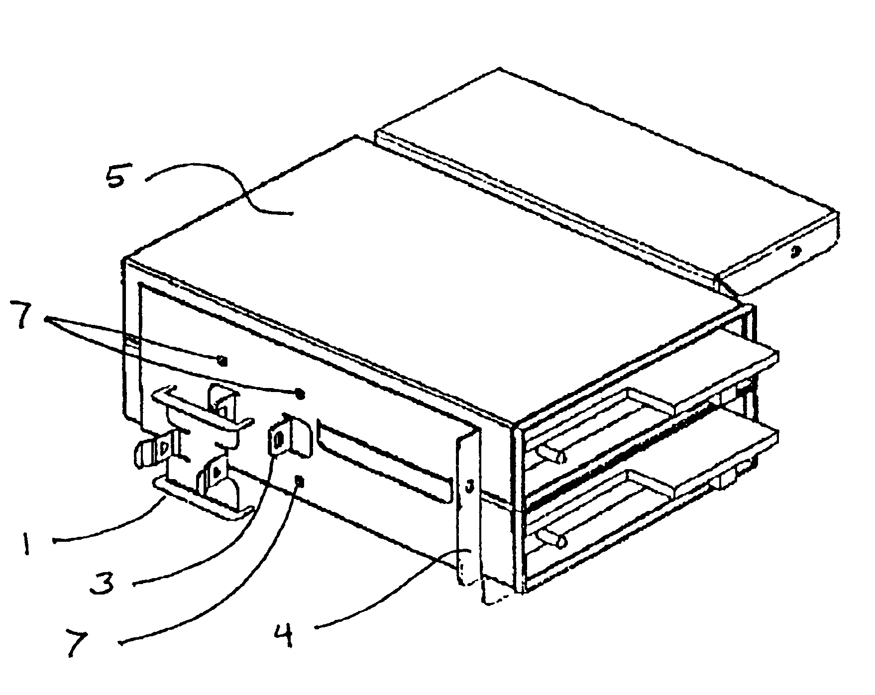
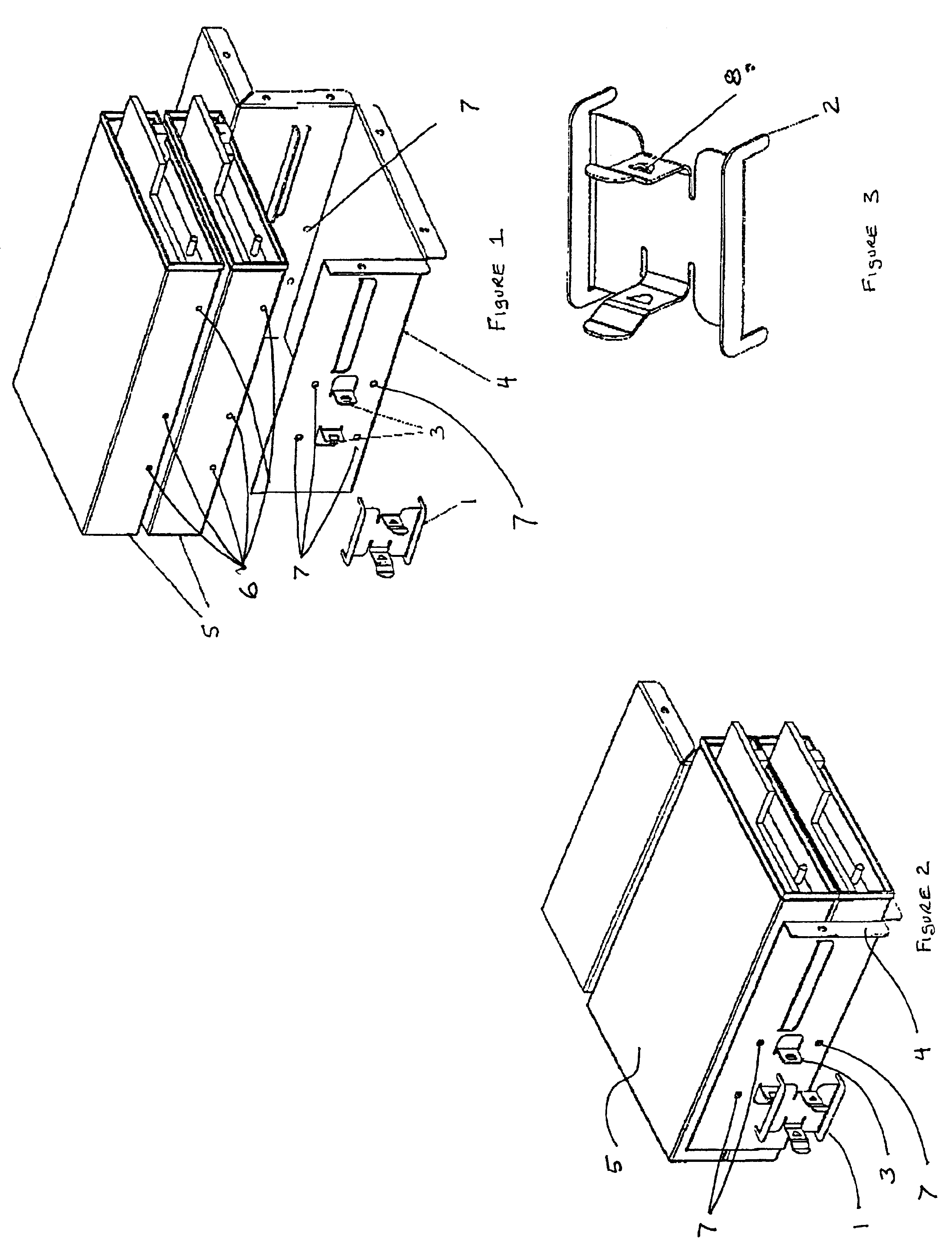
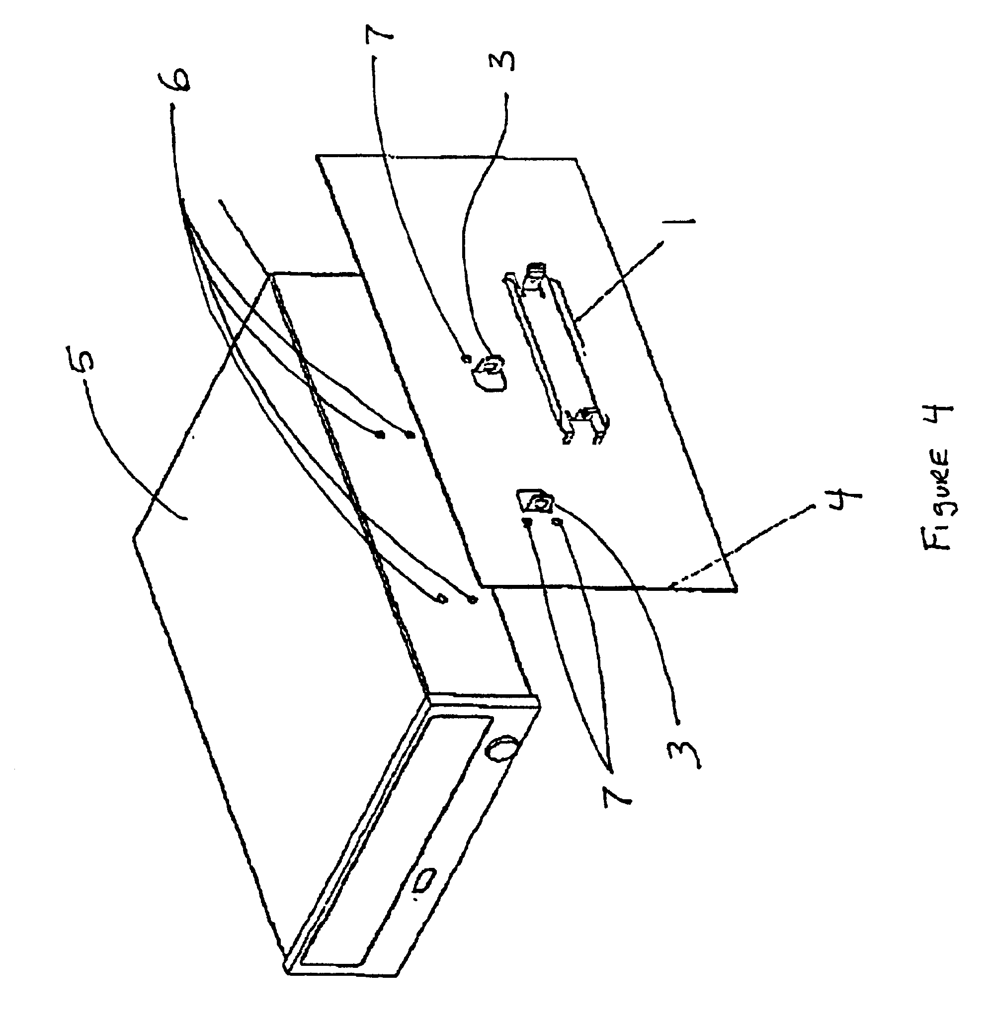
[0014]For a detailed description of the preferred embodiment of the present invention, please refer to FIGS. 1-4 in which like components are given like numbers for easy reference. FIG. 1 depicts the installation of two typical computer drives (5). Shown in FIG. 1 are the standardized screw holes (6) present on computer drives (5). The computer drives (5) are placed into the computer chassis (4) so that the standardized screw holes (6) are aligned with the pin alignment holes (7). The securing pins (2) of the securing clip (1) are positioned through the pin alignment holes (7) into the standardized screw holes (6). The securing clip (1) is attached to the computer chassis (4) using clip mounting features (3). The clip mounting features (3) engage flexible tabs (8) present on the securing clip (1).

[0015]FIG. 2 depicts the computer drives (5) after they have been installed into the computer chassis (4) but before the securing clip (1) has been attached to the clip mounting features (3...


PUM

PropertyMeasurementUnit
flexibleaaaaaaaaaa
sizeaaaaaaaaaa
electrical conductiveaaaaaaaaaa

Abstract

A computer drive securing system comprising a chassis for receiving and supporting a computer drive unit by one or more securing clips. The chassis includes one or more pinholes and one or more clip mounting features. The securing clip includes one or more securing pins and one or more flexible tabs for engaging the pinholes and clip mounting features of the chassis, respectively. The pins project into a screw hole or the like in the computer drive for releasably securing the computer drive to the chassis.

Description

CROSS REFERENCE TO RELATED APPLICATIONS[0001]This application is a regular application claiming priority of U.S. Provisional application Ser. No. 60 / 150,788 filed Aug. 26, 1999.BACKGROUND OF INVENTION[0002]1. Field of Invention[0003]This invention pertains to the design of a screw less, clip mounted computer drive. Specifically, in the present invention, a traditional drive mounting bracket or computer chassis is equipped with flexible tabs which secure a clip designed to engage and be locked into the standard screw holes located on the drive being attached.[0004]2. Description of Prior Art[0005]Historically, computer drives such as CD-ROMs, floppy disks, DVD drives and the like, were attached to the chassis of a computer using standard micro sized machine screws. While such method of attachment was secure and precise, it required significant amounts of labor. Further, even in the most careful of environments, damaged resulted to the other internal components of the computer due to ...

Claims


Application Information

Patent Timeline
Patent Type & Authority Patents(United States)
IPC IPC(8): G06F1/18G11B33/12
CPCG06F1/184G11B33/128G06F1/187Y10T29/49876
Inventor WILLIAMS, DAVE
Owner CARGILL INC
Why Eureka
Try Eureka