Three-axis magnetic sensor and method for manufacturing the same
a magnetic sensor and three-axis technology, applied in the field of three-axis magnetic sensors, can solve the problem of not having the desired characteristics of z-axis sensors, and achieve the effect of accurately determining the direction of a magnetic field, easy and inexpensiv
- Summary
- Abstract
- Description
- Claims
- Application Information
AI Technical Summary
Benefits of technology
Problems solved by technology
Method used
Image
Examples
first embodiment
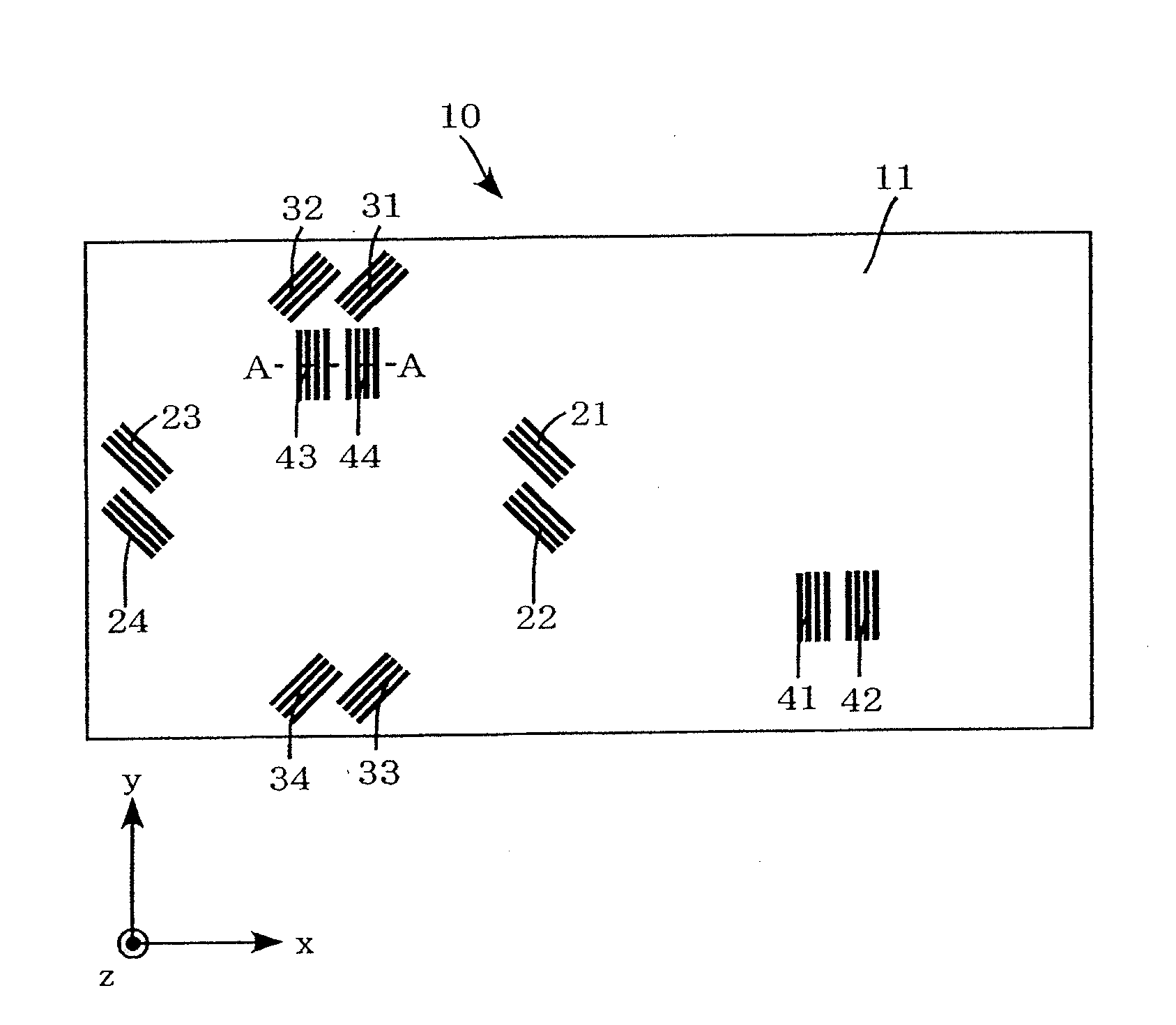
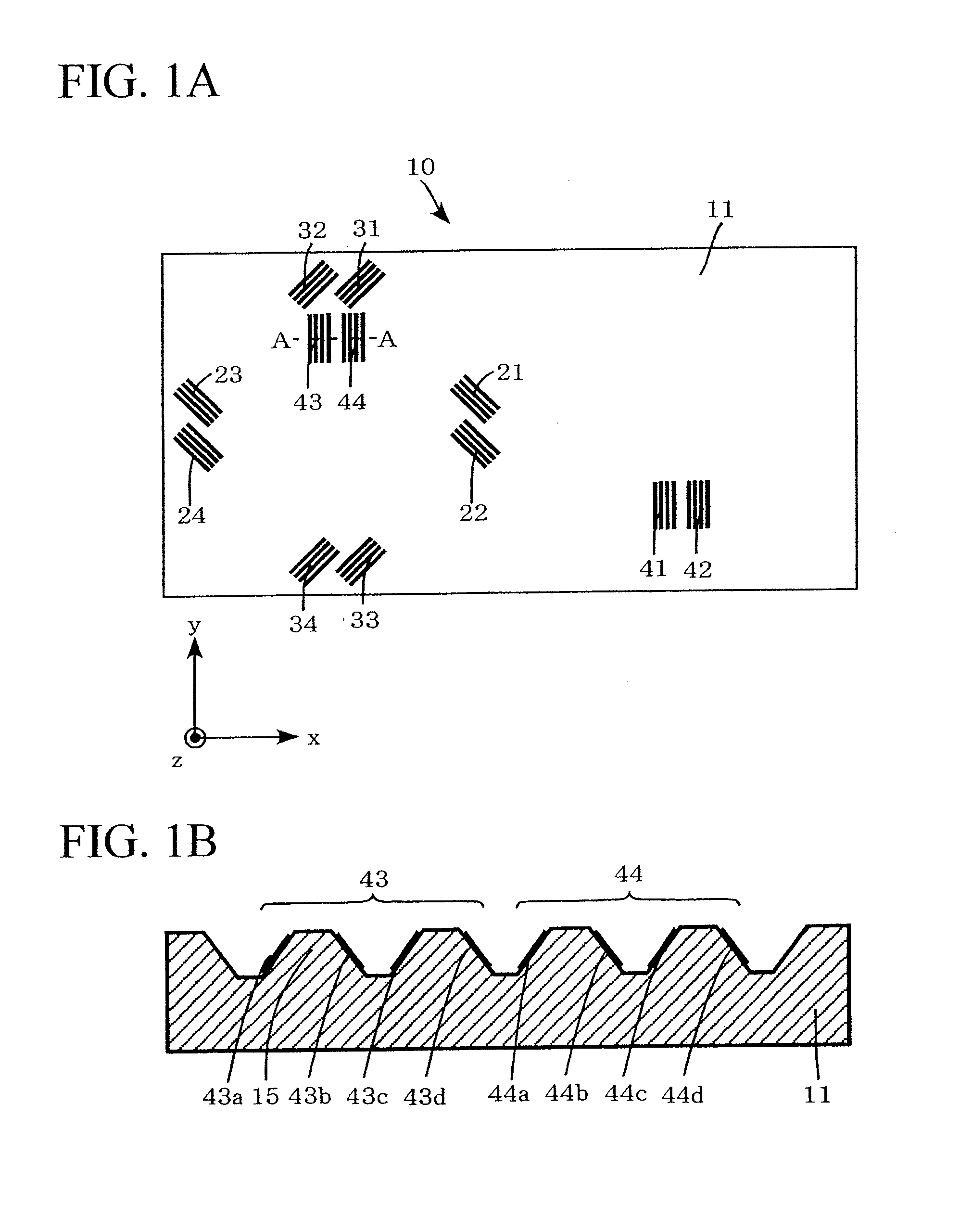
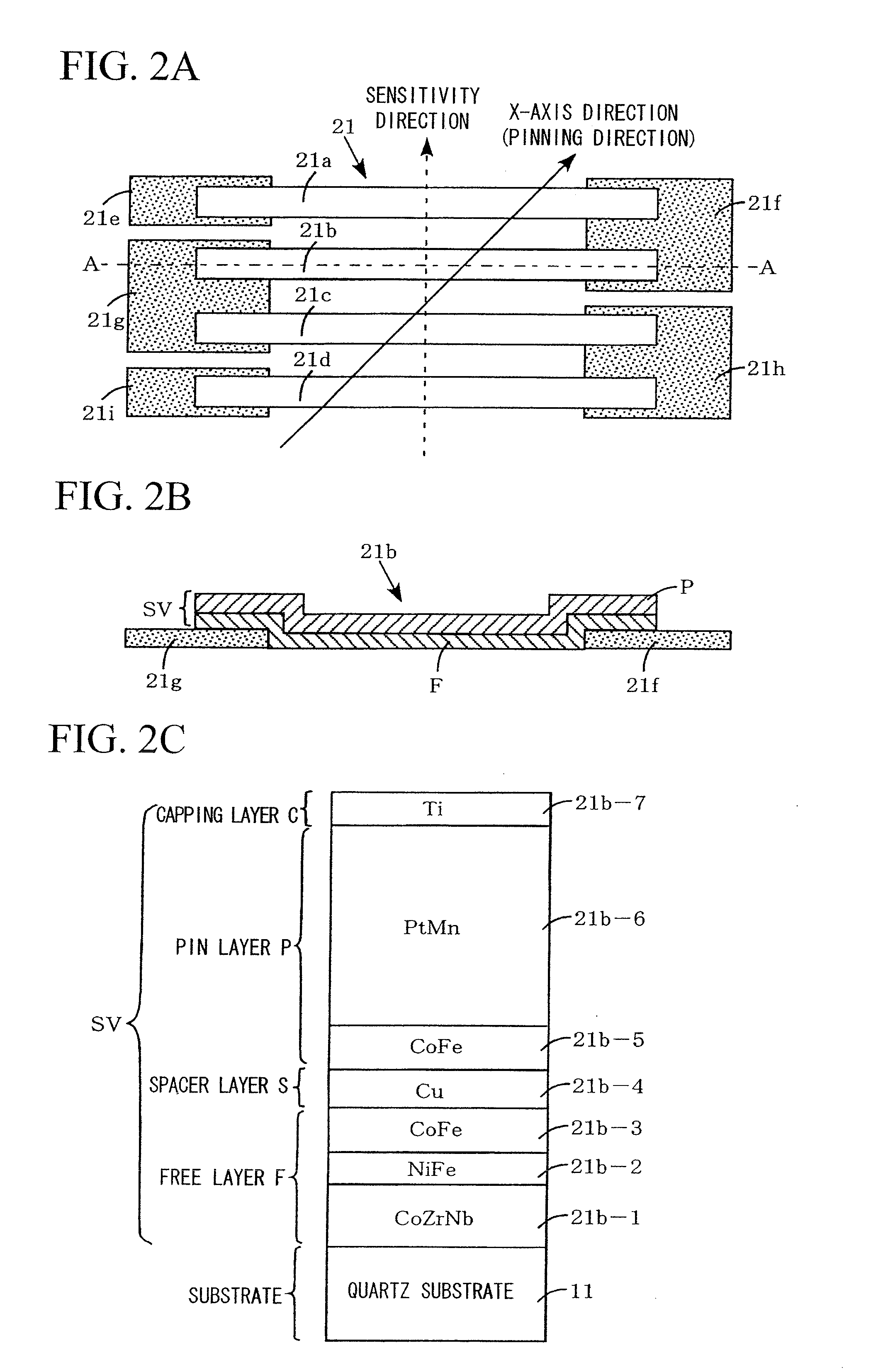
[0189]First, an explanation will be made of a three-axis magnetic sensor of a first embodiment as follows by referring to FIG. 1A to FIG. 15C.
[0190]As illustrated in FIGS. 1A and 1B, a three-axis magnetic sensor 10 of the first embodiment is provided with a substrate 11 made up of quartz or silicon, which is in a rectangular shape, with the sides along the X-axis and Y-axis orthogonal to each other, when viewed from above, (here, it is shaped so that the ratio of the short side (longitudinal) to the long side (transverse) (aspect ratio) is 1:2 and the side along the X-axis is a long side and the side along the Y-axis is a short side) and has a small thickness in the direction of the Z-axis orthogonal to the X-axis and the Y-axis. Then, a total of 12 GMR elements respectively made up of four elements of X-axis GMR elements 21 to 24, Y-axis GMR elements 31 to 34 and Z-axis GMR elements 41 to 44, a total of 12 pads (not illustrated) and connecting wires (not illustrated) connecting eac...
second embodiment
[0234]Next, an explanation will be made of a three-axis magnetic sensor of a second embodiment as follows by referring to FIG. 17A to FIG. 20C.
[0235]As illustrated in FIGS. 17A and 17B, a three-axis magnetic sensor 60 of the second embodiment is provided with a substrate 61 made with quartz or silicon which is in a rectangular shape with the sides along the X-axis and Y-axis orthogonal to each other, when viewed from above (here, it is shaped so that the ratio of the short side (longitudinal), to the long side (transverse) (aspect ratio) is 1:1.5 and the side along the X-axis is a long side and the side along the Y-axis is a short side) and has a small thickness in the direction of the Z-axis orthogonal to the X-axis and the Y-axis. It is possible to make the present sensor smaller in dimension than the three-axis magnetic sensor of the first embodiment by using the above-described substrate 61.
[0236]Then, a total of 12 GMR elements made up of respectively four elements of X-axis GM...
third embodiment
[0261]Then, an explanation will be made of the three-axis magnetic sensor of a third embodiment as follows by referring to FIG. 21A to FIG. 24B.
[0262]As illustrated in FIGS. 21A and 21B, a three-axis magnetic sensor 70 of the third embodiment is provided with a substrate 71 made with quartz or silicon which is in a square shape having the sides along the X-axis and Y-axis orthogonal to each other, when viewed from above, (namely, half in dimension as compared with the substrate 11 of the first embodiment) and has a small thickness in the direction of the Z-axis orthogonal to the X-axis and the Y-axis. It is possible to make the present sensor smaller in dimension than the three-axis magnetic sensor of the first embodiment and that of the second embodiment by using the above-described substrate 71.
[0263]Then, a total of ten GMR elements, namely, four each of the X-axis GMR elements 71a to 71d and the Y-axis GMR elements 71e to 71h and two Z-axis GMR elements 71i to 71j formed on a su...
PUM
| Property | Measurement | Unit |
|---|---|---|
| voltage | aaaaa | aaaaa |
| magnetoresistive effect | aaaaa | aaaaa |
| magnetization | aaaaa | aaaaa |
Abstract
Description
Claims
Application Information
 - R&D
- Intellectual Property
- Life Sciences
- Materials
- Tech Scout
- Unparalleled Data Quality
- Higher Quality Content
- 60% Fewer Hallucinations
Browse by: Latest US Patents, China's latest patents, Technical Efficacy Thesaurus, Application Domain, Technology Topic, Popular Technical Reports.
© 2025 PatSnap. All rights reserved.Legal|Privacy policy|Modern Slavery Act Transparency Statement|Sitemap|About US| Contact US: help@patsnap.com


