MS/MS Mass Spectrometer

a mass spectrometer and mass spectrometer technology, applied in the field of ms/ms mass spectrometer, can solve the problems of significant time delay, decrease in flight speed, and deterioration of analysis sensitivity, so as to improve detection sensitivity for product ions originating from a target ion, and improve the accuracy of the mass axis of the mass spectrum created in the measurement.

Active Publication Date: 2013-08-22
SHIMADZU CORP
View PDF0 Cites 22 Cited by
  • Summary
  • Abstract
  • Description
  • Claims
  • Application Information

AI Technical Summary

Benefits of technology

[0064]The MS / MS mass spectrometer according to any of the first through fifth aspects of the present invention can perform a neutral loss scan measurement or precursor ion scan measurement with a reduced influence from the time delay which occurs when the ions pass through the collision cell, whereby the detection sensitivity for product ions is improved over the entire mass-scan range, and the accuracy of the mass axis of a mass spectrum created in the measurement is also improved. In the case of an auto MS / MS measurement, the detection sensitivity for product ions originating from a target ion is improved, and the accuracy of the mass axis of a mass spectrum created in the measurement is also improved.
[0065]In particular, in the MS / MS mass spectrometer according to fourth or fifth aspect of the present invention, since the mass-scan operation is performed not only in the first mass spectrometer but also in the second mass separator in the process of obtaining mass analysis data for mass calibration, the electric field and other conditions which affect the ions until they arrive at the detector are approximately the same as those of the actual MS / MS analysis of a target sample. Therefore, the mass calibration accuracy is higher than in the case of obtaining the mass analysis data for mass calibration without performing the mass separation in the second mass separator.
[0066]In the MS / MS mass spectrometer according to the sixth, seventh or eighth aspect of the present invention, when a neutral loss scan measurement or precursor ion scan measurement is performed, the influence of an increase in the variation of the kinetic energy, which occurs while the ions pass through the collision cell, is reduced, so that the mass-resolving power for selecting the precursor ion can be adjusted to a target level. This makes it possible to improve the mass-resolving power for the precursor ion so as to correctly detect only the desired product ion, or to intentionally lower the mass-resolving power for the precursor ion so as to improve the detection sensitivity of the product ion.

Problems solved by technology

However, the following problem occurs since the dissociation of ions in the collision cell 14 occurs in the middle of their flight through a vacuum atmosphere:
When ions travel through a radio-frequency electric field under such a relatively high gas pressure, they gradually lose their kinetic energies due to collision with the gas, which decreases their flight speed.
Therefore, a significant time delay occurs when the ions pass through the collision cell 14.
This causes the mass-to-charge ratio of the neutral loss to be shifted from the intended value, with a possible deterioration in the analysis sensitivity.
This means that the mass axis of the mass spectrum may be significantly shifted, causing a problem in the quantitative or qualitative analysis based on the mass spectrum.
However, this broadens the time interval of a repetitive measurement and thereby increases the possibility of missing a component in an LC / MS or GC / MS analysis.
However, even when such a high-speed collision cell is used, ions require several milliseconds to pass through the cell, so that the aforementioned sensitivity deterioration or mass shift will inevitably occur when the mass-scan speed is increased to a level around 1000 u / sec or higher.Patent Document 1: JP-A 07-201304Patent Document 2: JP-B 3,404,849Non-Patent Document 1: API 4000™ LC / MS / MS System, [online], Applied Biosystems Japan Kabushiki Kaisha, [searched on Feb. 2, 2009], Internet Non-Patent Document 2: Tandem Quadrupole UPLC / MS Detector “ACQUITY™ TQD”, [online], Nihon Waters K. K., [searched on Feb. 2, 2009], Internet

Method used


Image

  • MS/MS Mass Spectrometer
  • MS/MS Mass Spectrometer
  • MS/MS Mass Spectrometer

Examples


first embodiment

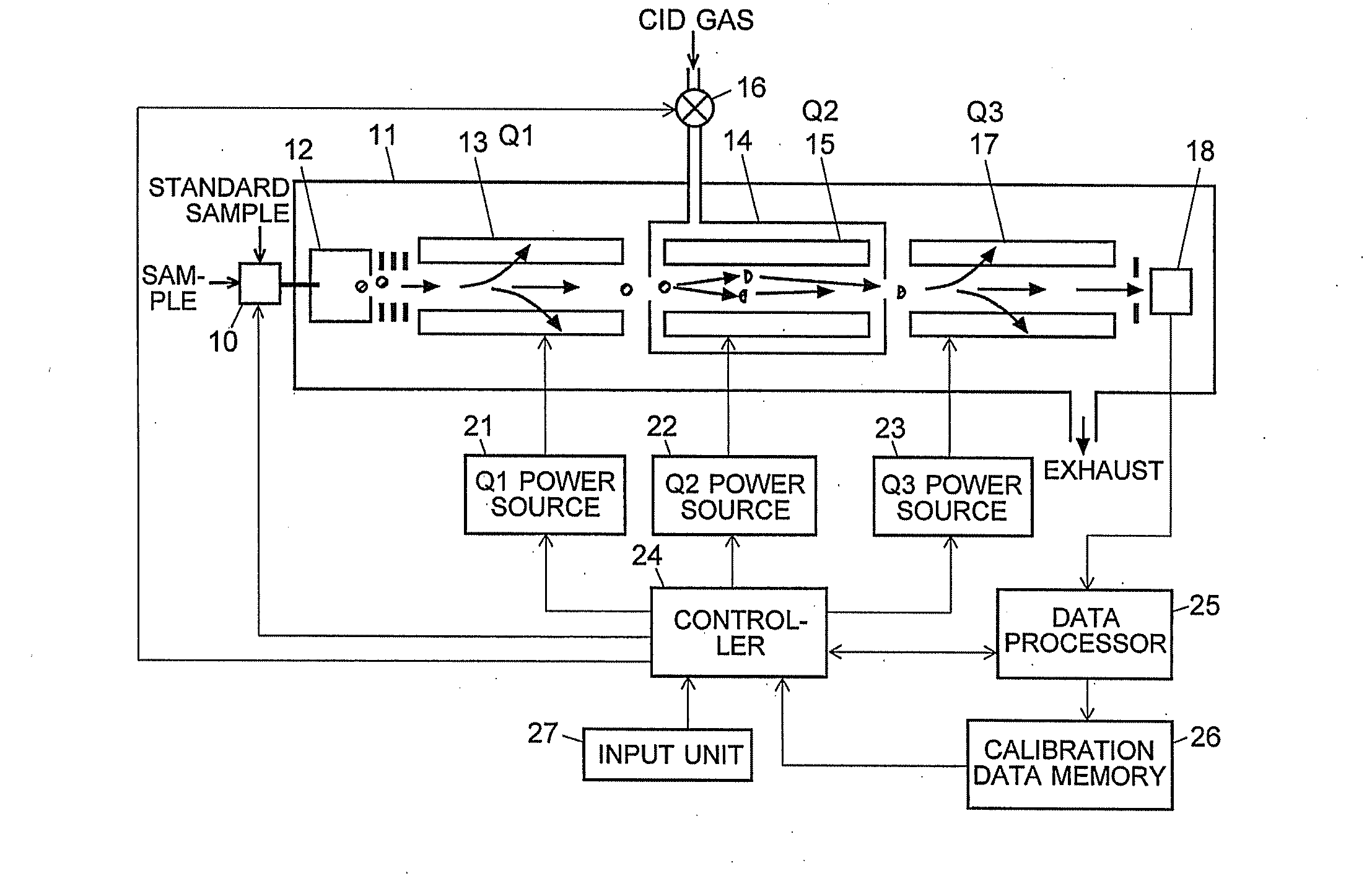
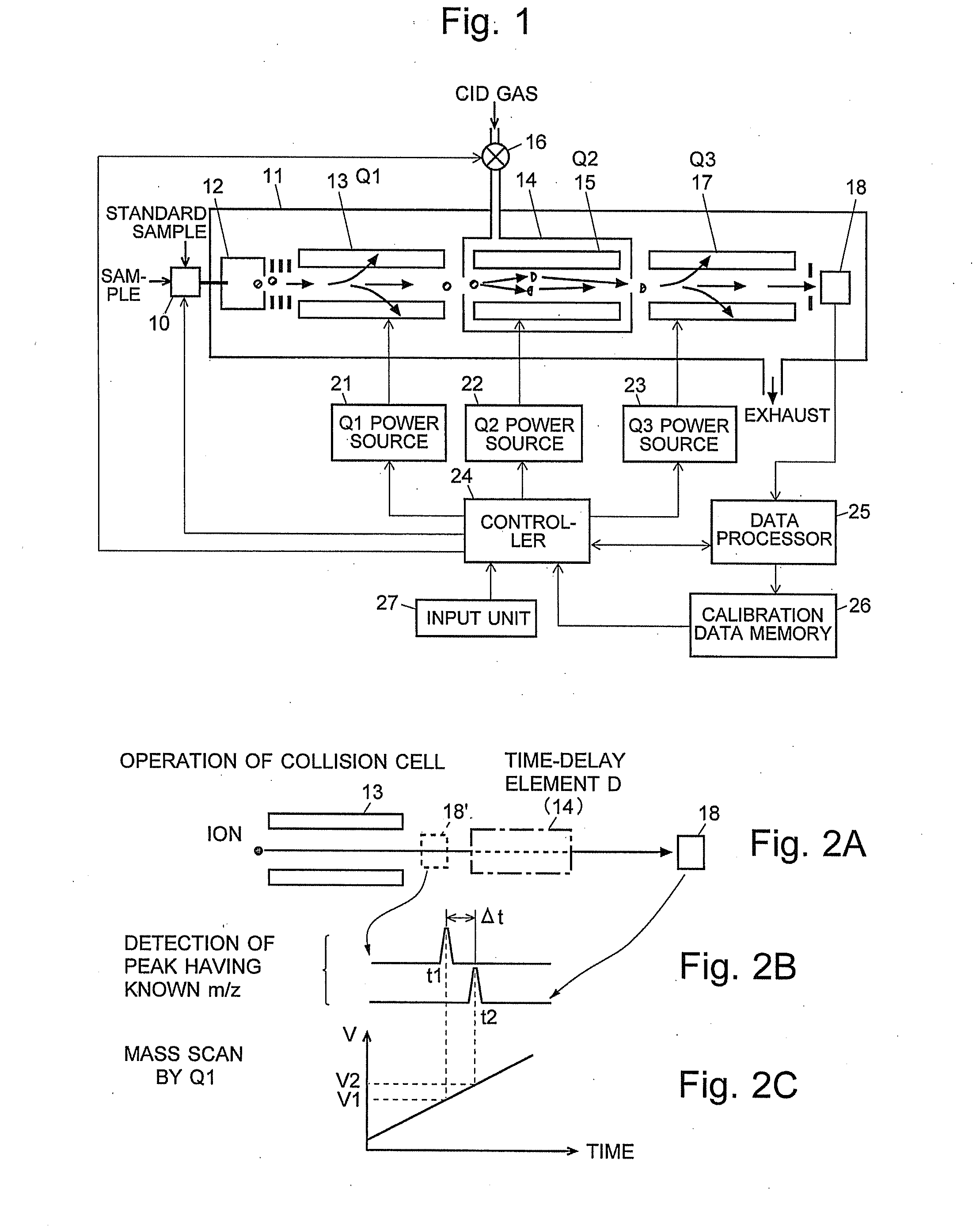
[0096]A triple quadrupole mass spectrometer as one embodiment (first embodiment) of the present invention is hereinafter described with reference to the attached drawings. FIG. 1 is a schematic configuration diagram of a triple quadrupole mass spectrometer of the present embodiment, and FIGS. 2A to 2C is model diagrams for explaining an operation characteristic of the triple quadrupole mass spectrometer of the present embodiment.

[0097]Similar to the conventional case, the triple quadrupole mass spectrometer of the present embodiment has a first-stage quadrupole 13 (which corresponds to the first mass separator of the present invention) and a third-stage quadrupole 17 (which corresponds to the second mass separator of the present invention), between which a collision cell 14 for dissociating a precursor ion to produce various kinds of product ions is located.

[0098]A Q1 power source 21 applies, to the first-stage quadrupole 13, either a composite voltage ±(U1+V1·cos ωt) including a DC...

second embodiment

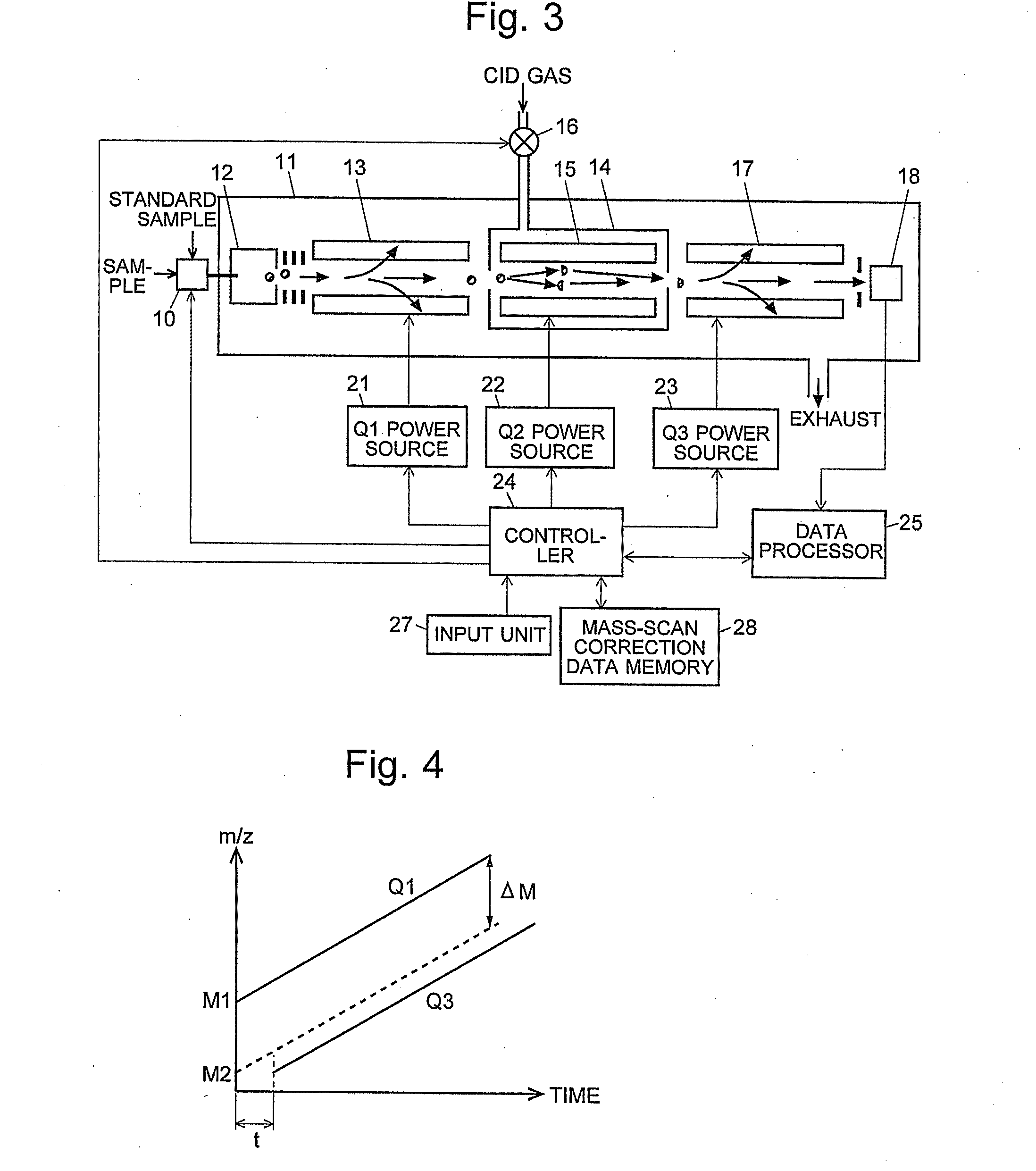
[0109]As another embodiment (second embodiment) of the present invention, a triple quadrupole mass spectrometer is hereinafter described by means of FIGS. 3 and 4. FIG. 3 is a schematic configuration diagram of the triple quadrupole mass spectrometer of the second embodiment, and FIG. 4 is a model diagram for explaining an operation characteristic of the triple quadrupole mass spectrometer of the second embodiment. In FIG. 3, the same components as used in the previously described triple quadrupole mass spectrometer of the first embodiment are denoted by the same numerals. In the triple quadrupole mass spectrometer of the second embodiment, a mass-scan correction data memory 28, in which a set of predetermined correction data is previously stored, is connected to the controller 24.

[0110]As already explained, when a CID gas is introduced into the collision cell 14 to dissociate ions, the ions undergo a significant time delay when passing through the collision cell 14. To address this...

third embodiment

[0112]As yet another embodiment (third embodiment) of the present invention, a triple quadrupole mass spectrometer is hereinafter described by means of FIG. 5. FIG. 5 is a model diagram showing an operation characteristic of the triple quadrupole mass spectrometer of the third embodiment. The configuration of the present triple quadrupole mass spectrometer is basically identical to that of the second embodiment and hence will not be described.

[0113]In the case of the triple quadrupole mass spectrometer of the second embodiment, the delay time t for initiating the mass-scan operation of the third-stage quadrupole 17 under various dissociating conditions is stored as correction data in the mass-scan correction data memory 28. By contrast, in the triple quadrupole mass spectrometer of the third embodiment, a set of data for correcting the mass-to-charge ratio difference in the mass-scan operation is stored in the mass-scan correction data memory 28. That is to say, when a time delay of...


PUM


Abstract

A mass analysis of a sample having a known mass-to-charge ratio is carried out by performing a scan at a first-stage quadrupole over a predetermined mass range, under the condition that a collision induced dissociation gas is introduced into a collision cell and a voltage applied to a third-stage quadrupole is set so that no substantial mass separation occurs in this quadrupole. Various product ions originating from a precursor ion selected by the first-stage quadrupole arrive at and are detected by a detector without being mass separated. Accordingly, based on the detection data, a data processor can obtain a relationship between the voltage applied to the first-stage quadrupole and the mass-to-charge ratio of the selected ions, with a time delay in the collision cell reflected in that relationship. This relationship is stored in a calibration data memory, to be utilized in a neutral loss scan measurement or the like.

Description

TECHNICAL FIELD[0001]The present invention relates to an MS / MS mass spectrometer for dissociating an ion having a specific mass-to-charge ratio (m / z) by Collision-Induced Dissociation (CID) and for performing a mass analysis of product ions (fragment ions) generated by the dissociation.BACKGROUND ART[0002]An MS / MS analysis (which may also be referred to as a tandem analysis) is known as one of the mass spectrometric methods for identifying a substance with a large molecular weight and for analyzing its structure. A triple quadrupole (TQ) mass spectrometer is a typical MS / MS mass spectrometer. FIG. 6 is a schematic configuration diagram of a generally used triple quadrupole mass spectrometer disclosed in Patent Documents 1, 2 or other documents.[0003]This mass spectrometer has an analysis chamber 11 evacuated by a vacuum pump (not shown). In this chamber 11, an ion source 12 for ionizing a sample to be analyzed, three quadrupoles 13, 15 and 17, each of which is composed of four rod e...

Claims


Application Information

Patent Timeline
Patent Type & Authority Applications(United States)
IPC IPC(8): H01J49/00
CPCH01J49/0009H01J49/429H01J49/4215H01J49/004
Inventor OKUMURA, DAISUKE
Owner SHIMADZU CORP
Why Eureka
Try Eureka