Air vent apparatus for blocking light

a technology of air vents and light sources, which is applied in the field of air vents, can solve the problems of severe restrictions, unrestricted air flow, and undesirable increase in the amount of heat buildup of light sources or and achieve the effect of reducing the amount of heat buildup of light sources and other heat emitting components in the interior of the device housing

Inactive Publication Date: 2003-01-21
SEIKO EPSON CORP
View PDF6 Cites 30 Cited by
  • Summary
  • Abstract
  • Description
  • Claims
  • Application Information

AI Technical Summary

Problems solved by technology

The concurrent requirement of minimizing or preventing the escape of direct light from the device works against designing air vents that allow unrestricted air flow.
This is especially undesirable for a presentation projector device, since the light will interfere with the darkening of the presentation room required for proper viewing of the projected presentation.
Alternatively, if the louver angle is too steep or the depth of the louvers too deep (i.e. if the length of the vanes of the louver are too long), then the air flow is severely restricted.
While this has the effect of blocking the escape of at least some of the direct light, it results in an undesirable increase in the amount of heat buildup from the light source or other heat emitting components in the interior of the device housing. FIGS. 1a-1b illustrate an example of the latter type of prior art projector air vent 100.
At the same time, some direct light can still escape 130, thus interfering with the proper viewing of the projected presentation.
Another drawback of prior art air vent designs is the reliance on increased fan speed to overcome the air flow restriction of vent designs that attempt to block direct light from escaping.
This has the undesirable effect of increasing the noise produced by the device.
In the context of a presentation projection device, the noise can interfere with the effective use of the device to deliver a presentation in a conference room setting.
On the other hand, the challenge of designing a vent that minimizes the restriction of air flow while blocking direct light requires a complex analysis of the causes of air flow restriction through the vent: flow between parallel plates (the flow along the surfaces of the parallel louvers that comprise the vent), flow contraction at the entrance to the vent, and changing the direction of the flow (the angle of the louvers measured from a perpendicular to the vent).
So increasing the speed of a fan to increase the air flow velocity will only result in a proportionate increase in the pressure loss through the air vent 200.
However, shallower angles also will not block as much direct light as the steeper angles, an undesirable result.
An air vent design that takes into account all of these factors and requirements presents a unique set of challenges, requiring a new and novel solution.

Method used


Image

  • Air vent apparatus for blocking light
  • Air vent apparatus for blocking light
  • Air vent apparatus for blocking light

Examples


Embodiment Construction

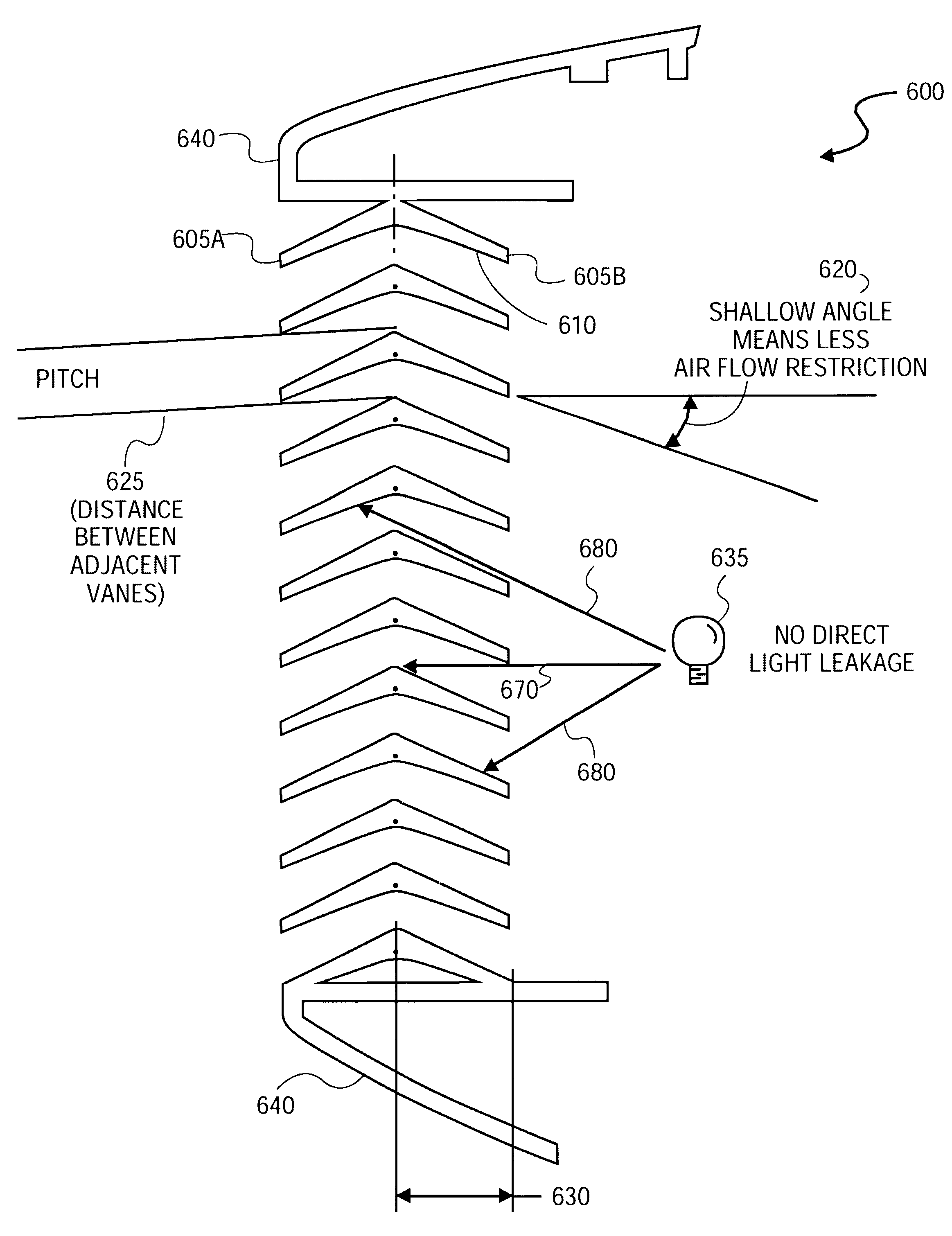
Referring now to FIG. 7, wherein an example of one embodiment of an air vent 700 that blocks light using a pitch size of 4.5 mm is illustrated. A single chevron 710 having vanes 705a and 705b is disposed asymmetrically within the vent housing (not shown) such that the vane 705b extending towards the device's interior 740 is substantially perpendicular to the vent housing (not shown) and substantially parallel to the direction of the flow of air 750. At a vane length of 12 mm 730 an optimal vane angle of 28.25 degrees 720 is employed to block direct light while at the same time substantially minimizing the restriction of the air flow 750 through the vent 700. The vane angle is measured from a perpendicular 760 to the vent housing (not shown).

Depending on the requirements of the device, variations in the vane length 730 and vane angle 720 for a given pitch of 4.5 mm may be employed. A table illustrating the range of optimal vane lengths 730 and vane angles 720 is illustrated in Table ...


PUM


Abstract

An air vent apparatus for blocking light is provided for devices requiring a light source for generating light, such as a presentation projector, an arc lamp, a laser device and the like. The improved air vent apparatus employs a stacked chevron design to minimize the restriction of the flow of air through the air vent while blocking the escape of direct light. In one embodiment of the present invention, the stacked chevron is symmetrically disposed in the air vent housing of the device. In another embodiment of the present invention, the stacked chevron is asymmetrically disposed in the air vent housing so that a vane of the chevron extending towards the interior of the air vent is substantially perpendicular to the air vent housing and substantially parallel to the source of the flow of air. The use of a stacked chevron design allows the air vent in the device housing be constructed with vanes having a range of shallower angles than those of prior art vents so as to minimize the restriction of the flow of air through the vent, while at the same time blocking all or nearly all of the direct light emitted from the device's light source. Numerous variations in the length of the vanes of the chevron (i.e. the depth of the air vent), the vane angle, and the pitch (i.e. the distance between the stacked chevrons) may be employed to achieve a suitably optimal vent for a number of different devices, including presentation projectors, arc lamps, laser devices and the like.

Description

1. Field of the InventionThe present invention relates generally to air vents for ventilating a device having a light source. More specifically, the present invention relates to an air vent that blocks direct light emitted from the light source without substantially restricting the flow of air through the vent.2. Background InformationDevices requiring a light source for generating light, such as a projection display apparatus, an arc lamp, a laser device and the like, need to be ventilated to dissipate heat generated by the light while minimizing or preventing the escape of direct light emitted by the device. These types of devices are therefore typically equipped with an air vent.The air vent permits the exchange of warm air from the interior of the device for cooler air exterior to the device. Projection display apparatuses in particular are often further equipped with fans to increase the air flow so as to accelerate the exchange of air. Thus it is important to provide air vents...

Claims


Application Information

Patent Timeline
Patent Type & Authority Patents(United States)
IPC IPC(8): F24F13/08
CPCF24F13/082Y10S454/905F24F2221/02
Inventor WILSON, CLARK
Owner SEIKO EPSON CORP
Why Eureka
Try Eureka