Rotor production method including assembling a slot insulator and coil trunk into a set prior to insertion into an armature core

a production method and a technology for rotors, applied in the direction of manufacturing stator/rotor bodies, magnetic circuit rotating parts, magnetic circuit shape/form/construction, etc., can solve the problems of inability to ensure the insulation of the coil trunk, the face of the slot is exposed, and the deformation or destructibility of the lower layer slot insulator

Inactive Publication Date: 2003-01-28
DENSO CORP
View PDF11 Cites 10 Cited by
  • Summary
  • Abstract
  • Description
  • Claims
  • Application Information

AI Technical Summary

Problems solved by technology

However, according to the above integrating method, there poses the following problem in order to insert the coil trunks of the coil bars into the slots after inserting the slot insulators into the slots of the armature core.
As a result, when, for example, the lower layer slot insulator is produced by a soft material in a thin film shape, it is conceivable that the lower layer slot insulator may be deformed or destructed easily by the interference with the coil arm.
Further, when the slot insulator is integrated to shift in the axial direction in respect of the slot, although one end of the slot insulator in the axial direction is projected from the end face of the armature core, the other end of the slot insulator is recessed from the end face of the armature core and therefore, the wall face of the slot is exposed and the insulation in respect of the coil trunk cannot be ensured.
Further, although a method of positioning the slot insulator in the axial direction in respect of the slot by arranging a positioning member on the side of the end face of the armature core and bringing one end of the slot insulator in contact with the positioning member, is possible, when the slot insulator is produced by a soft material in a thin film shape, the rigidity of the slot insulator is deficient and therefore, the accurate positioning may not be carried out since the side of the one end of the slot insulator which is brought into contact with the positioning member is deformed.
When the coil trunk is inserted into the slot under this state, the coil arm interferes with the deformed portion of the slot insulator and the coil trunk cannot be integrated into the slot with certainty.
Further, when the slot insulator is shifted in the axial direction in accordance with the deformation of the one end side, the other end side of the slot insulator is recessed into the slot and the wall face of the slot is exposed and therefore, the coil trunk may not be insulated from the armature core with certainty.

Method used


Image

  • Rotor production method including assembling a slot insulator and coil trunk into a set prior to insertion into an armature core
  • Rotor production method including assembling a slot insulator and coil trunk into a set prior to insertion into an armature core
  • Rotor production method including assembling a slot insulator and coil trunk into a set prior to insertion into an armature core

Examples


embodiment 2

According to the embodiment, the slot insulator holding portion 18 formed at the combining blocks 15 is formed at the midway of the coil trunk path portion 16a in a shape opened in a V-like form and is inclined by a predetermined angle.

A step of integrally combining the lower layer slot insulator 4 and the lower layer coil bar 8 is performed as follows.

First, the lower layer slot insulator 4 is inserted to the slot insulator holding portion 18 formed in the combining blocks 15 and is set to a predetermined position. As shown in FIG. 15, the lower layer slot insulator 4 can be inserted into the slot insulator holding portion 18 from above the combining blocks 15. Alternatively, it may be inserted from the inlet of the coil inserting path 16. Further, the lower layer slot insulator 4 set to the slot insulator holding portion 18 is held in an attitude inclined by a predetermined angle.

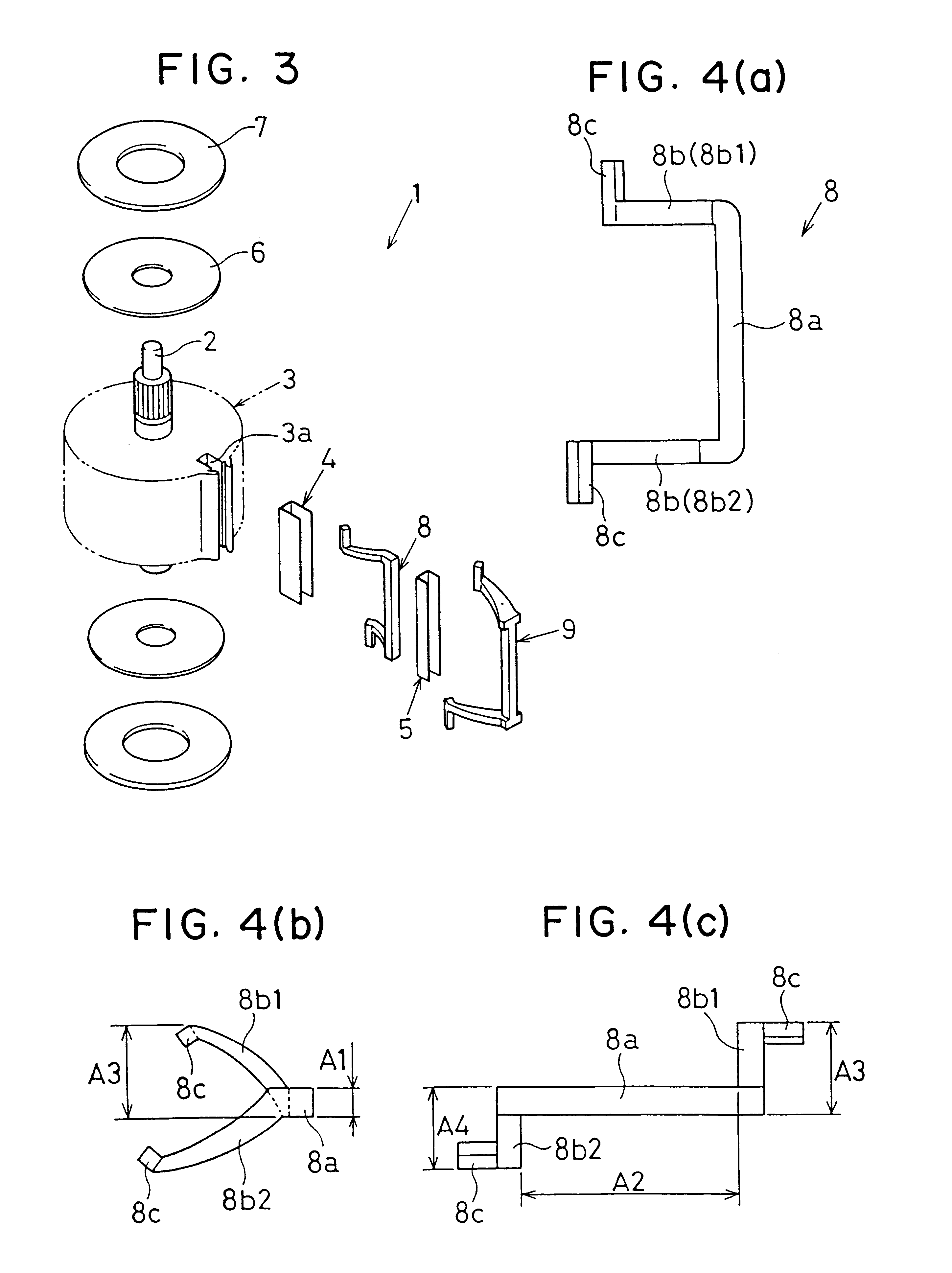
Successively, the lower layer coil bar 8 is inserted from the inlet of the coil inserting path 16 and ...

embodiment 3

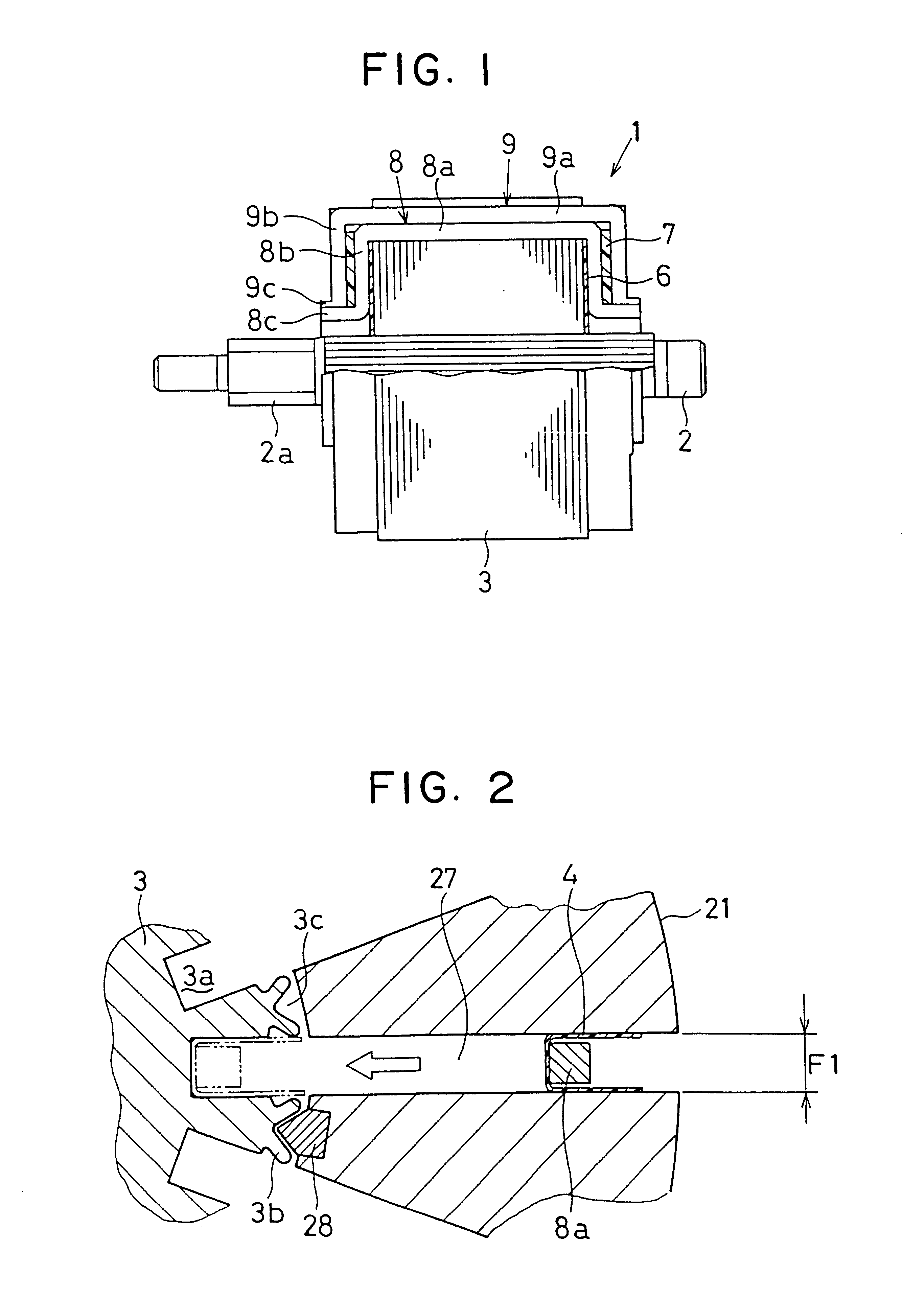
In this embodiment, the lower slot insulator 4 and the lower layer coil bar 8 are combined in the coil integrating path 27 of the coil holding member 11 without using the combining jig 10 described in the first embodiment and the second embodiment, and are inserted to the slot 3a as they are.

According to the coil holding member 11, the coil integrating paths 27 are formed among the coil holding blocks 21 arranged in the circumferential direction at constant intervals and at the midway of each of the coil integrating paths 27, a space (slot insulator holding portion 18) for setting the lower layer slot insulator 4 is provided. As shown in FIG. 19, in respect of the coil integrating path 27, the opening width H on the inlet side of the slot insulator holding portion 18 is formed to be slightly larger than the width A1 of the coil trunk 8a and the opening width I on the outlet side of the slot insulator holding portion 18 is formed to be slightly larger than a dimension of the width A1...

embodiment 4

In this embodiment, as shown in FIG. 20, in respect of the lower layer slot insulator 4, front end sides 4c are bent to the outer side by an arbitrary angle from midways of both of the side face portions 4b. Alternatively, as shown in FIG. 21, the front end sides 4c are shaped in a form bent to the outer side by an arbitrary radius of curvature from the midways of both of the side face portions 4b.

Meanwhile, as shown in FIG. 22, in respect of the upper layer slot insulator 5, the section is bent substantially in a U-like shape and both of the side face portions 5b are shaped in a form slightly opened toward the outer side. Further, the width J on the outer side of the bottom portion 5a of the upper layer slot insulator 5 is set to be smaller than a minimum width K of the inner side of the opening portion of the lower layer slot insulator 4.

In the integrating method of the embodiment, the lower layer slot insulator 4 and the lower layer coil trunk 8a are combined and the both members...


PUM

PropertyMeasurementUnit
shapeaaaaaaaaaa
lengthaaaaaaaaaa
thicknessaaaaaaaaaa

Abstract

A production method of a rotor in which a lower layer slot insulator is held at a slot insulator holding portion of a combining jig, a lower layer coil bar is inserted into a coil inserting path of the combining jig and is combined integrally with the lower layer slot insulator by being pushed by a first coil inserting arrow and thereafter, set to inside of a coil integrating path of a coil holding member. The coil holding member is attached to a coil inserting device along with an armature core. The lower layer slot insulator and a lower layer coil trunk are integrally inserted into a slot of the armature core by pushing the lower layer coil bar set to inside of the coil integrating path. The upper layer coil trunk and the lower layer coil trunk may be formed integrally with respective coil arms as a single coil bar.

Description

1. Field of the InventionThe present invention relates to a production method and a production apparatus for a rotor which is produced by combining a slot insulator and a coil bar to a rotor core.2. Description of Related ArtJapanese Patent Application No. 7-326983 (U.S. Pat. No. 5,778,512) discloses a method of integrating or assembling coil bars (lower layer coil bars and upper layer coil bars) each in a channel-like shape having a linear coil trunk and a pair of coil arms and slot insulators (lower layer slot insulators and upper layer slot insulators) for insulating the coil trunks inserted into slots of a rotor (armature) core from the armature core, to the armature core.However, according to the above integrating method, there poses the following problem in order to insert the coil trunks of the coil bars into the slots after inserting the slot insulators into the slots of the armature core.That is, the slot insulators are not positioned in the axial direction in respect of th...

Claims


Application Information

Patent Timeline
Patent Type & Authority Patents(United States)
IPC IPC(8): H02K15/06H02K15/10H02K15/00
CPCH02K15/066H02K15/10Y10T29/49073Y10T29/49009Y10T29/49011Y10T29/49012
Inventor EBIHARA, JIROTAKIGUCHI, MASAYUKI
Owner DENSO CORP
Why Eureka
Try Eureka