
High security cylinder lock and key

a high-security, cylinder lock technology, applied in the field of high-security cylinder locks and keys, can solve the problems of not always available required additional shell space in the conventional cylinder lock design, and the inability to replace the core design

Inactive Publication Date: 2003-03-04
MEDECO SECURITY LOCKS
View PDF9 Cites 58 Cited by
  • Summary
  • Abstract
  • Description
  • Claims
  • Application Information

AI Technical Summary

Benefits of technology

is to provide a cylinder lock that can be used in a removable core design where the locking mechanism does not extend into the upper half of the shell or interfere with the locking tab or other mechanism that locks a removable core cylinder lock into a surrounding shell.

Problems solved by technology

Although this solution is effective, it requires additional space in the shell for the additional pin chambers, springs and pins that fit within the chambers.
The required additional space in the shell is not always available for conventional cylinder lock designs.
To add a secondary conventional pin tumbler mechanism to a primary pin tumbler locking mechanism is not an option for a removable core design.
Nonetheless, it is difficult to fit a supplemental locking mechanism entirely within the plug.
This leaves only limited space within the plug.
The space available in the plug is particularly limited in the radial direction, which is the direction needed to accommodate a conventional pin-tumbler design in which a coil spring is axially aligned with a locking pin.
Other known types of supplemental or secondary locking mechanisms are expensive to manufacture or cannot be integrated into existing installed systems in the field.
Yet another problem with conventional cylinder locks relates to the manner in which the key is aligned relative to the locking mechanisms in the lock.
This would make copying a key more difficult.

Method used


Image

  • High security cylinder lock and key
  • High security cylinder lock and key
  • High security cylinder lock and key

Examples


Embodiment Construction

)

In describing the preferred embodiment of the present invention, reference will be made herein to FIGS. 1-14 of the drawings in which like numerals refer to like features of the invention.

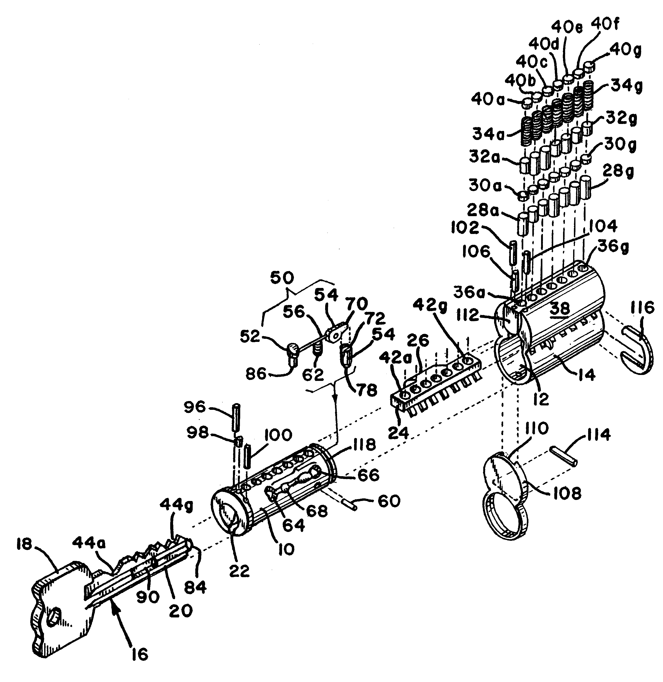
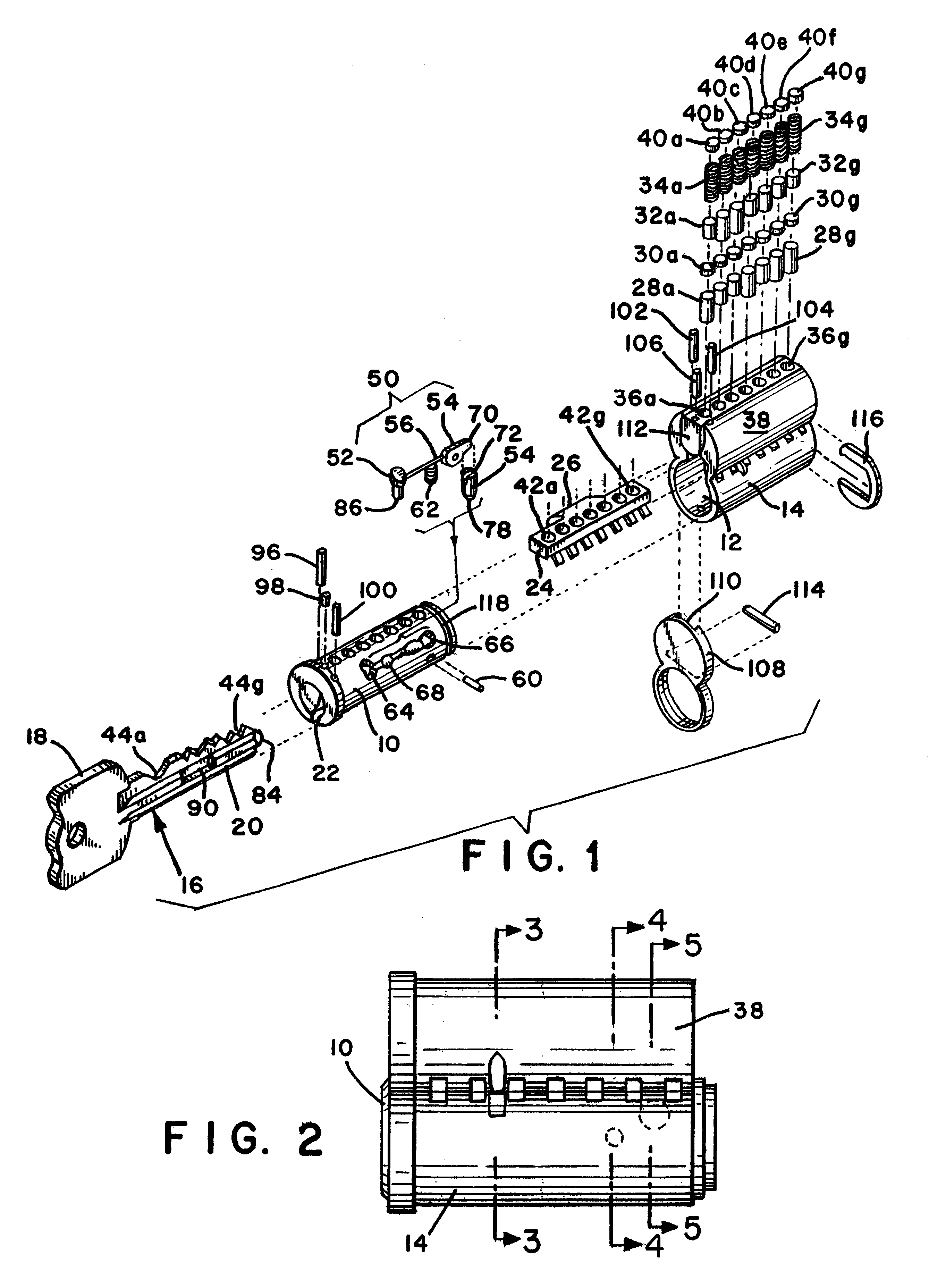
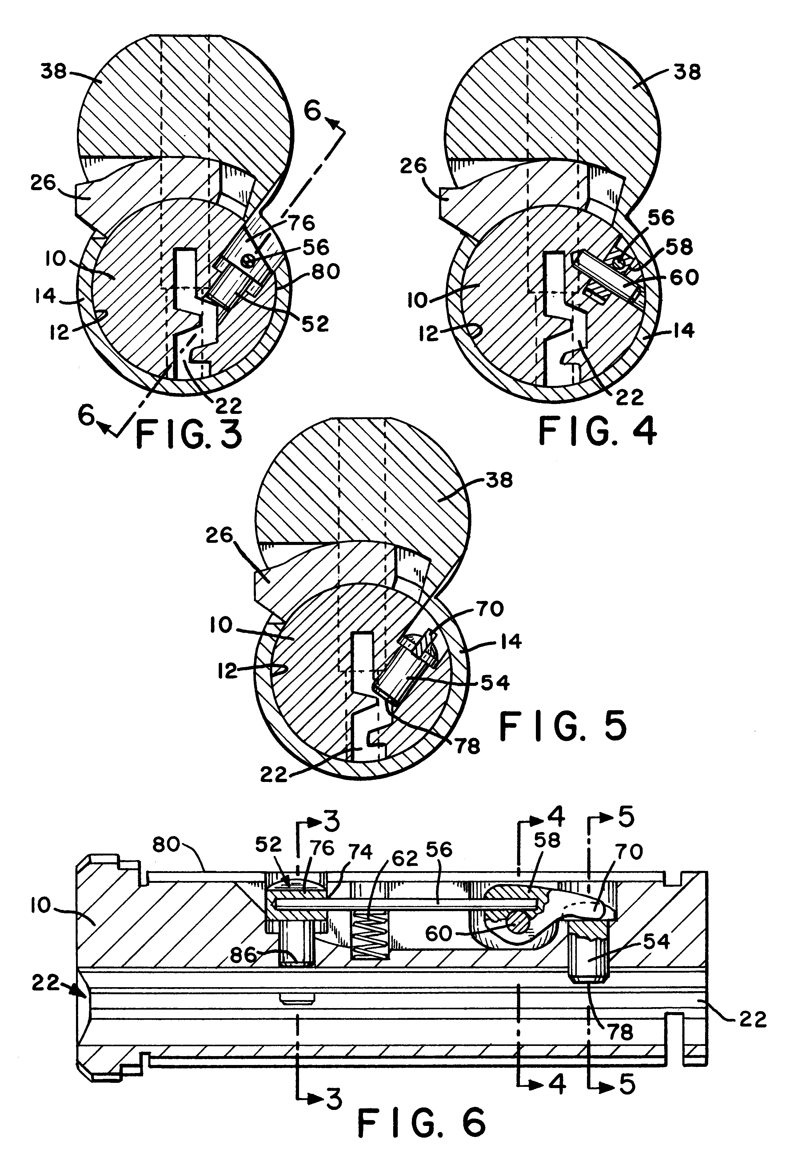
Referring to FIG. 1, the present invention includes a cylinder lock mechanism having a cylindrical plug 10 inserted into a substantially cylindrical opening 12 in a shell 14. A key 16 for operating the lock includes a key bow 18 and a key blade 20. The cross section of the key blade (see FIG. 8) matches the cross sectional shape of the key slot 22 in the plug 10.

In the preferred design shown in FIG. 1, the cylinder lock is a removable core cylinder lock, however, the invention may also be used in non-removable core applications. In a removable core design, the entire shell 14 is inserted into a matching opening in an outer casing (not shown). The shell 14 is locked into the casing by a locking tab 24 that can be rotated counterclockwise and locked into place to extend rectangular projection 26 out...


PUM


Abstract

A cylinder lock includes a shell and a plug inside the shell. A locking pin, a sensor pin and a flexible coupling are mounted within the plug. The sensor pin moves the flexible coupling and the coupling moves the locking pin to an unlocked position when the correct key is inserted into a key slot in the plug. The key includes a locking pin receiving notch, to allow the locking pin to move to the unlocked position. The key also includes a contact surface that moves the sensor pin and thereby moves the locking pin to the unlocked position through the flexible coupling. When an incorrect key, without the locking pin receiving notch, is inserted, the flexibility of the flexible coupling allows the sensor pin to move without moving the locking pin. The cylinder lock may also include conventional pin tumblers. The receiving notch of the key may be provided with an alignment surface that cooperates with the locking pin to control the depth the key is inserted into the lock and allow keys of varying length to align relative to the pin tumblers of the cylinder lock.

Description

1. Field of the InventionThe present invention relates to high security cylinder locks and keys for such locks. More particularly, the present invention relates to cylinder locks that use an additional independent locking mechanism to supplement a conventional pin tumbler locking mechanism.2. Description of Related ArtCylinder locks include a cylindrical plug that turns inside a shell. The plug is provided with a key slot and is connected at one end to a mechanism to be operated by the cylinder lock. Inserting the correct key and rotating the plug relative to the shell operates the lock mechanism. Preventing the plug from rotating relative to the shell keeps the mechanism locked.In a conventional cylinder lock the plug is locked relative to the shell with a pin tumbler mechanism including multiple pins located in a series of evenly spaced pin chambers that extend across the shear surface at the interface between the plug and the shell. Each pin chamber includes at least a lower pin,...

Claims


Application Information

Patent Timeline
Patent Type & Authority Patents(United States)
IPC IPC(8): E05B27/00E05B9/00E05B9/08E05B15/16E05B15/00E05B19/00
CPCE05B9/084E05B27/0035E05B15/1614E05B27/0053E05B19/0017Y10T70/7605Y10T70/7616Y10T70/7655Y10T70/7881Y10T70/7932Y10T70/7944
Inventor SHVARTS, VLADIMIR
Owner MEDECO SECURITY LOCKS
Learn More