Vice device in compound miter saw

a technology of miter saw and blade, which is applied in the direction of metal sawing device, manufacturing tools, drawing boards, etc., can solve the problems of insufficient high fence, difficult to cut a crown member whose breadth is too wide for the crown member to be put against the low fence,

Inactive Publication Date: 2003-04-08
KOKI HLDG CO LTD
View PDF10 Cites 43 Cited by
  • Summary
  • Abstract
  • Description
  • Claims
  • Application Information

AI Technical Summary

Problems solved by technology

Due to this, the fence cannot be set sufficiently high, that is, generally, it is set low.
Therefore, when the crown member is cut while it set against a fence, the compound miter saw is able to cut only the crown member having such a breadth which allows the crown member to be put against a low fence and it is difficult to cut a crown member the breadth of which is too wide for the crown member to be put against the low fence.

Method used


Image

  • Vice device in compound miter saw
  • Vice device in compound miter saw
  • Vice device in compound miter saw

Examples


Embodiment Construction

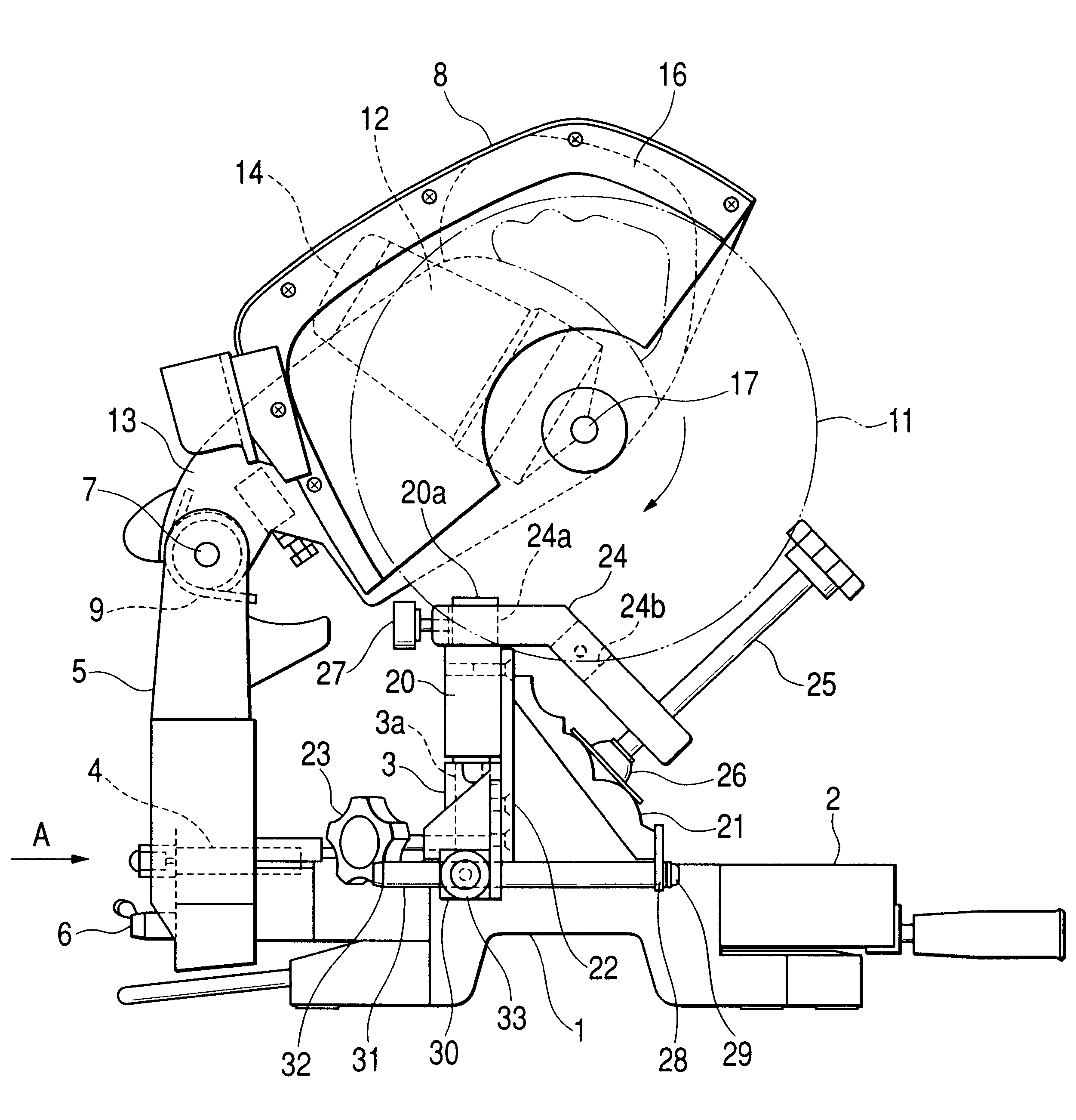
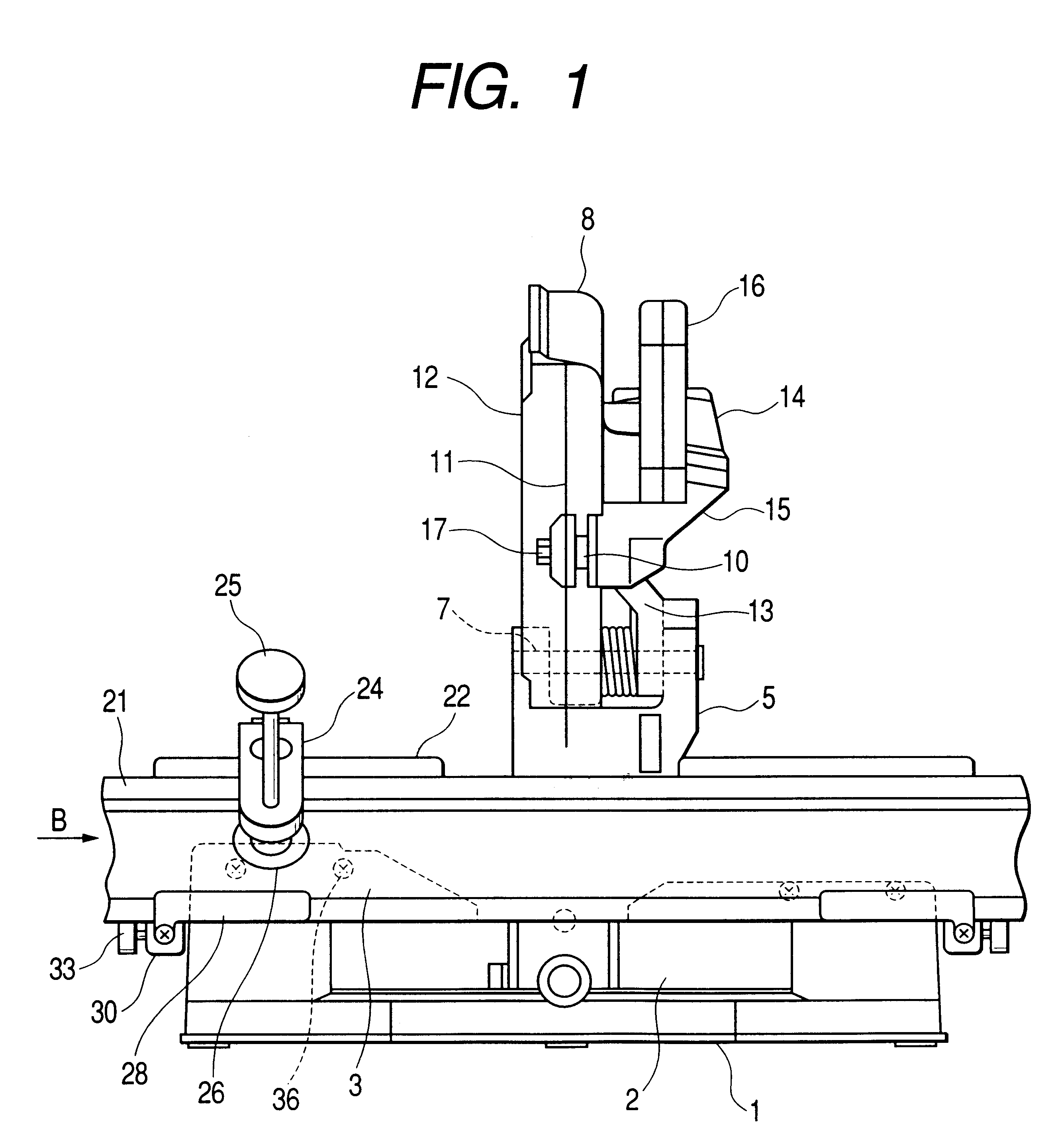
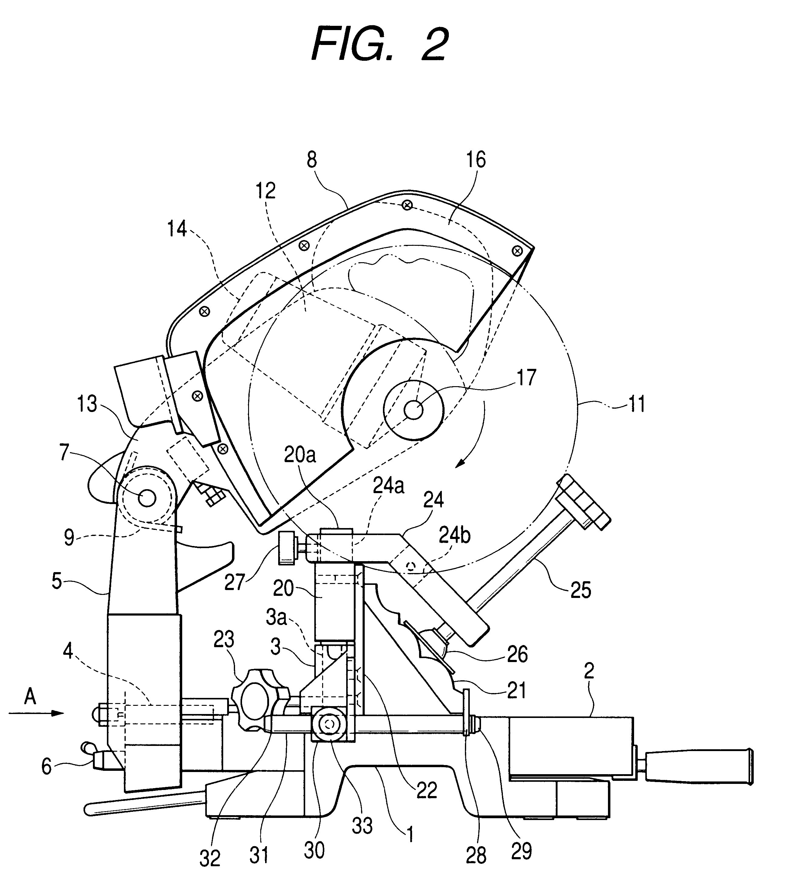
Now, description will be given below of an embodiment of a vice device according to the invention with reference to FIGS. 1 to 7.

In the present embodiment, in the central portion of a base 1, there is embedded a turn table 2 in such a manner that it can be rotated in the horizontal direction, while the upper surface of the turn table 2 is set flush with the upper surface of the base 1. On the upper surfaces of the base 1 and turn table 2, there can be set a workpiece such as a crown member 21 or a rectangular member 37. In the present invention, members (in the present embodiment, the base 1 and turn table 2) on which the workpiece can be set are generically referred to as a base part. On the upper surface of the base 1, there is fixed a fence 3 which is used to support the end face of the workpiece.

On the rear end portion of the turn table 2, there is erected a holder 5 through a holder shaft 4, the axis of the holder shaft 4 is positioned so as to be almost identical with the uppe...


PUM

PropertyMeasurementUnit
angleaaaaaaaaaa
angleaaaaaaaaaa
pressure angleaaaaaaaaaa

Abstract

The vice device includes a vice holder 24 composed of two side parts connected together at a given angle and, in these two side parts of the vice holder 24, there are respectively formed two holes 24a, 24b which extend at right angles to their associated side parts. By selectively switching these holes 24a, 24b over to each other, the pressing direction of a vice plate 26 can be changed.

Description

1. Field of the InventionThe present invention relates to a vice device for use in a compound miter saw suitable to cut not only an ordinary member to be cut (that is, a workpiece to be cut) having a rectangular-shaped section (which is hereinafter referred to as a rectangular member) but also an ornamental long extrusion member (a crown-molding member: an ornamental long extrusion member to be mounted along corner portions between a ceiling and walls; some of the such crown-molding members have a mounting angle .theta. thereof with respect to the ceiling that is set in the range of 38.degree.-45.degree.. This is hereinafter referred to as a crown member).2. Description of the Related ArtA compound miter saw of this type for cutting the above crown member is disclosed in U.S. Pat. No. 4,875,399. This compound miter saw is structured so as to have a stopper for supporting the counter-fence side front end of the crown member. That is, when cutting the crown member, the stopper is posi...

Claims


Application Information

Patent Timeline
Patent Type & Authority Patents(United States)
IPC IPC(8): B23D45/04B23D47/04B23D47/00B23D45/00B27B9/00B27B5/20
CPCB23D47/04B23D45/044Y10T83/7788Y10T83/7697Y10T83/758Y10T83/762Y10T83/75Y10T83/7684Y10T83/7487Y10T83/7693
Inventor HAYASHIZAKI, TOSHIHIKOOZAWA, HIROMIOKA, EISAKU
Owner KOKI HLDG CO LTD
Why Eureka
Try Eureka