Sun shield for vehicles

a technology for vehicles and sun shields, applied in vehicle bodies, monocoque constructions, building components, etc., can solve problems such as additional injuries for vehicle occupants

Inactive Publication Date: 2003-06-03
MULLER HERMANN FRANK
View PDF9 Cites 48 Cited by
  • Summary
  • Abstract
  • Description
  • Claims
  • Application Information

AI Technical Summary

Problems solved by technology

Solar modules which are applied to glass may cause additional injuries for vehicle occupants in case of a front-end collision.

Method used


Image

  • Sun shield for vehicles
  • Sun shield for vehicles
  • Sun shield for vehicles

Examples


Embodiment Construction

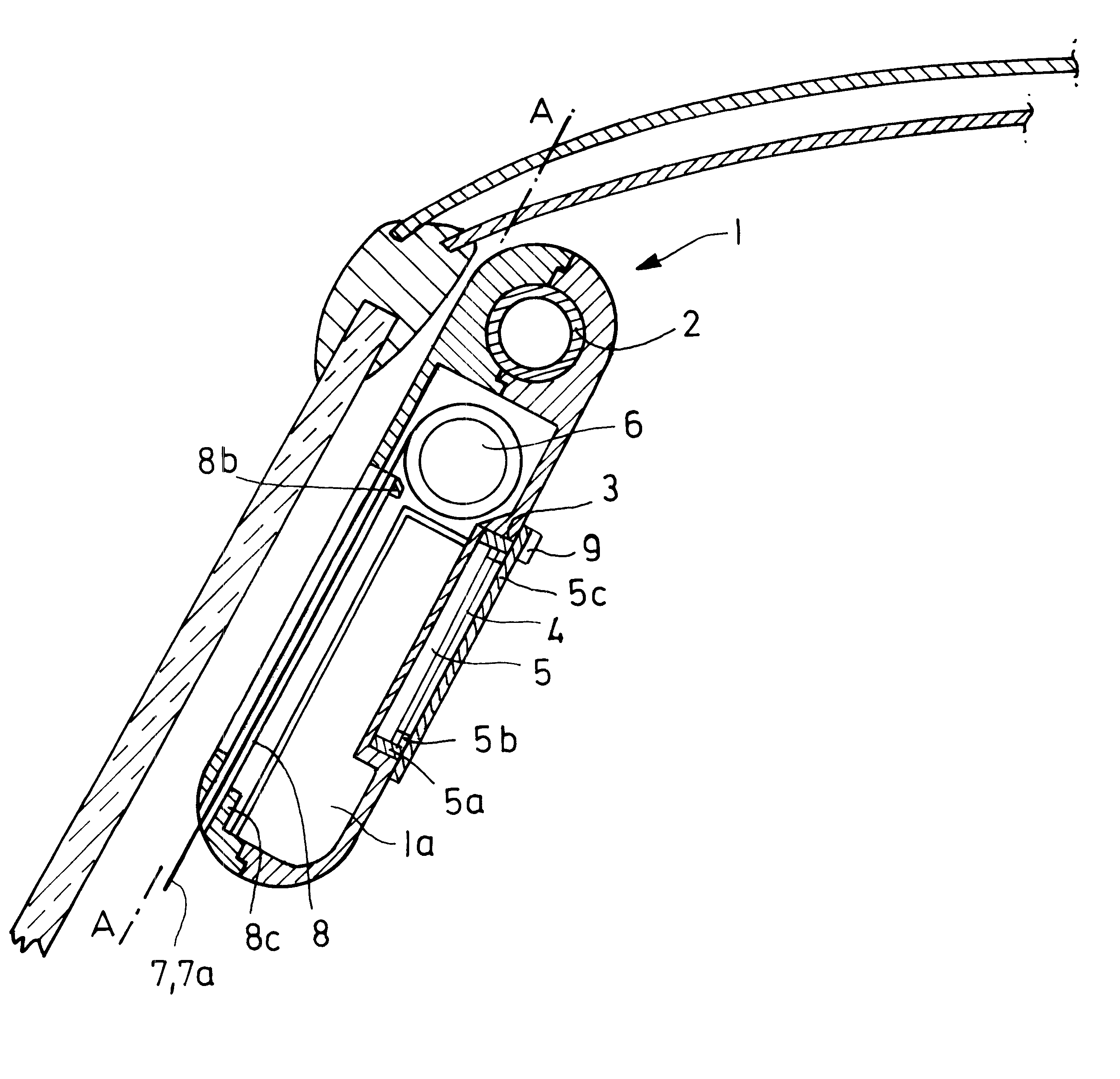
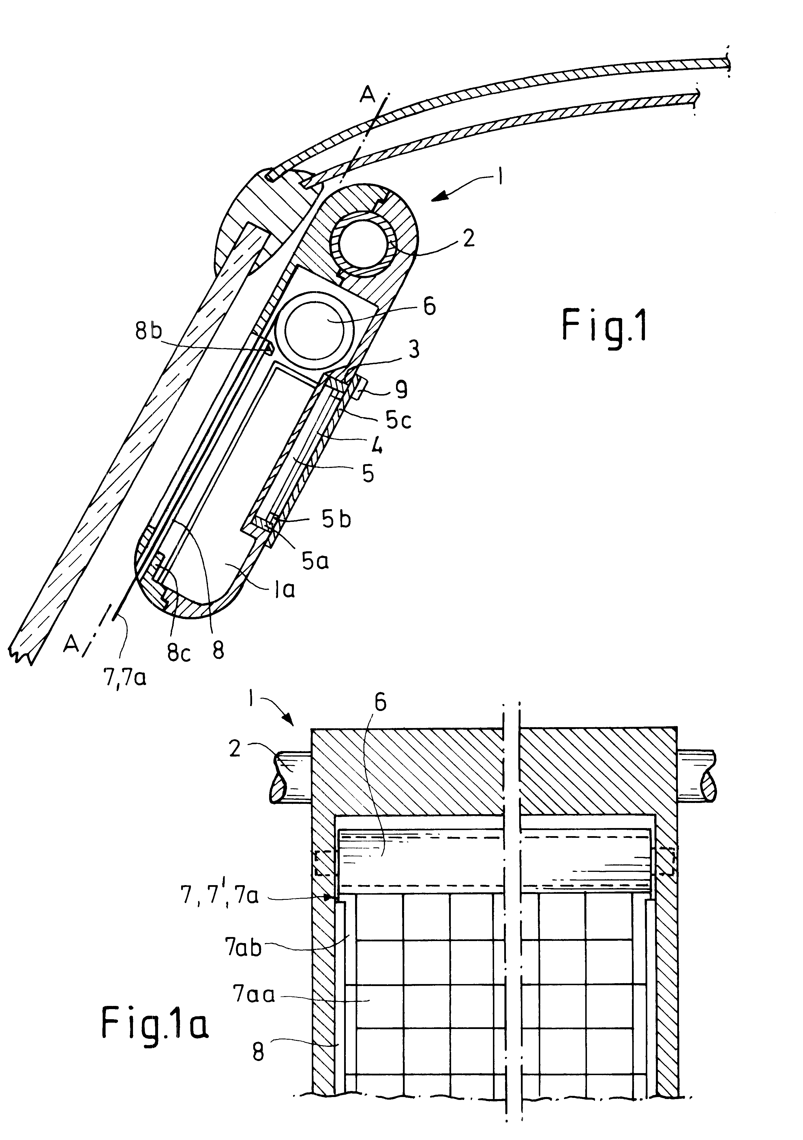
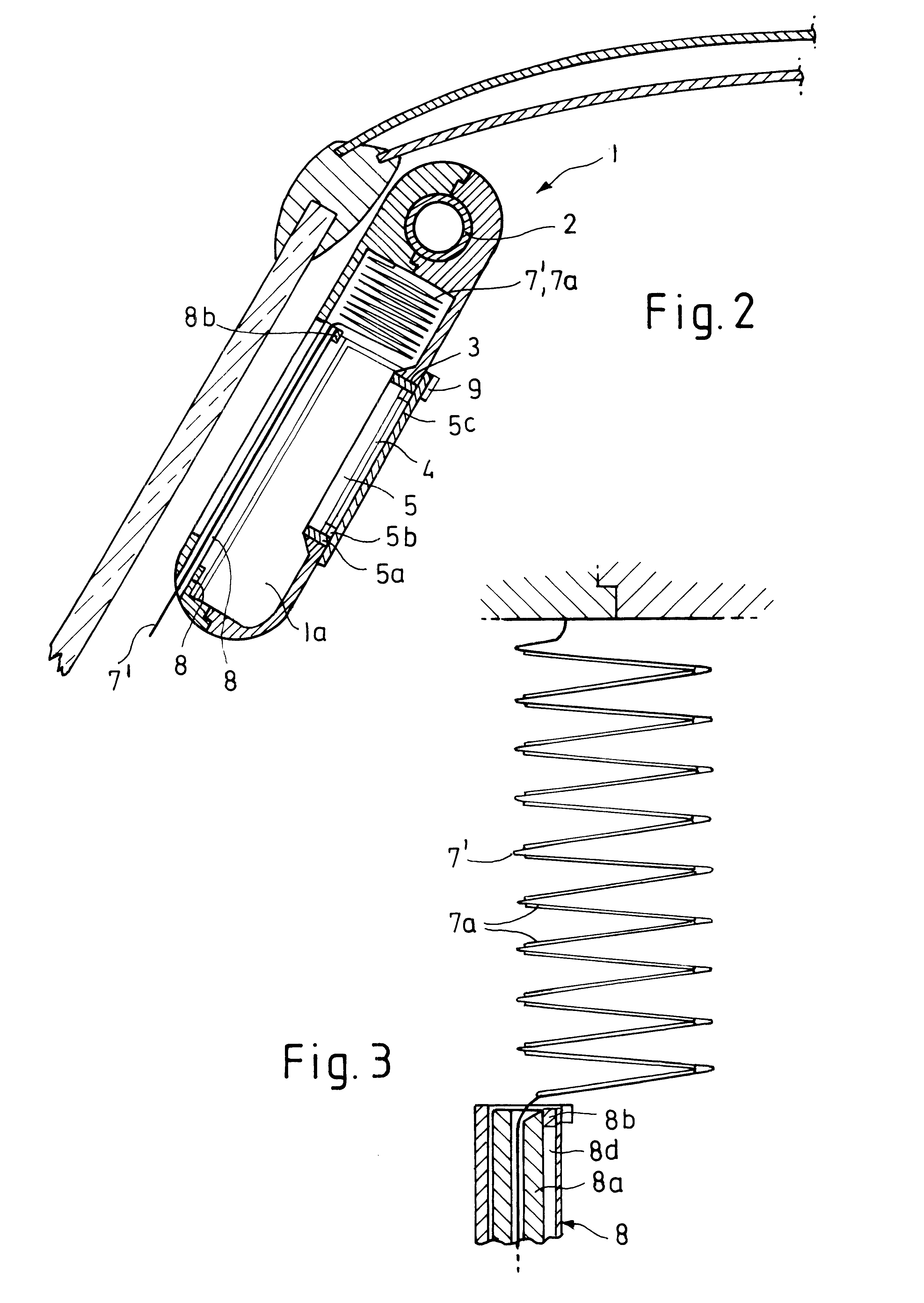
The inventive sun shield (1)--according to FIG. 1--shows (as known from DE 4003 399 C2) a bar (2) at its upper longitudinal edge. The sun shield is swivelling around that bar (2) and is snapped into the vehicle ceiling at its bended end. Naturally, in this connection constructively altered swivel-and-snap-in variants are possible.

The sun shield--according to DE 40 03 399 C2--shows on its back side facing the vehicle interior an opening for installing batteries for storage of energy gained from the solar cells. The further development--according to DE 198 55 258 A 1--refers to assign a planar component part for that opening such as an illuminated cosmetic mirror with a removable frame which can be used as a component unit together with integrated solar modules, battery(ies) and mini lamps on the vehicle exterior. The mirror can be used as a flashlight if necessary. This further developed sun shield consists of--in contrast to a sun shield according to U.S. Pat. No. 6,012,757--two hou...


PUM


Abstract

A sun shield, having disengageable swivel bearing, rollable and flexible solar modules on a support material made of scrim tissue or taffeta with layer material to form a laminate, organic (OLED) or polymer (PLED) luminous diodes, has a small cross section in which for an enlargement of the solar surface the support material with thin-layer elements is arranged to be extended and retracted from the sun shield. A component which can be snapped in the opening on the back of the sun shield can be disengaged and used as a flashlight outside the vehicle.

Description

1. Field of the InventionThe invention refers to removable sun shields with solar modules to convert impinging light into electrical energy.2. Description of the Prior ArtSuch solar modules are described in DE 40 03 399 C2 and DE 198 55 258 A1. Solar modules which are applied to glass may cause additional injuries for vehicle occupants in case of a front-end collision. Gratings made of plastic for installing foam material for upholstery as well as flat component parts such as cosmetic mirrors and LEDs and / or LCDs for illumination make the sun shield relatively thick.Therefore, it is the invention's objective to suggest a sun shield which--in addition to the already described utilization--is made slender even on the outside of the vehicle with a design which is optionally adjustable. The removable illuminated cosmetic mirror or the like can also be used as a flashlight for even a longer time period with the assistance of one solar cell. Furthermore, possible injuries in case of front...

Claims


Application Information

Patent Timeline
Patent Type & Authority Patents(United States)
IPC IPC(8): B60J3/02B60Q3/02B60Q3/00F21S9/00F21S9/03F21L2/00
CPCB60J3/0204B60Q3/0226F21L2/00F21S9/037B60Q3/0269F21W2101/08B60Q3/252B60Q3/59F21W2106/00
Inventor MULLER, HERMANN-FRANK
Owner MULLER HERMANN FRANK
Why Eureka
Try Eureka