Switch device and method of assembling switch device

a switch device and switch technology, applied in the field of switch devices, can solve the problems of difficult to control the dimensions of each of the parts, and difficult to make the spacing dimension shorter than the standard spacing,

Inactive Publication Date: 2003-06-17
KK TOKAI RIKA DENKI SEISAKUSHO
View PDF6 Cites 14 Cited by
  • Summary
  • Abstract
  • Description
  • Claims
  • Application Information

AI Technical Summary

Problems solved by technology

First, the two operation knobs 2, 3 require many parts since the operation knobs 2, 3 are arranged side by side being formed separately. The knob holders 2a, 3a and the knobs 2b, 3b are combined with each other to form each of the operation knobs 2, 3. In this case, the knob holders 2a, 3a and the knobs 2b, 3b of each of the operation knobs 2, 3 are fitted to each other wish some play present therebetween. Moreover, to guide the movement of the operation knobs 2, 3, a predetermined clearance is required between the knob holders 2a, 3a and the guide ribs 1b and between the knobs 2b, 3b and the opening 1a. Since many parts are required in the configuration, it is difficult to control the dimensions of each of the parts. For this reason, to prevent interference between the operation knobs 2, 3 caused by the play, the spacing dimension A (refer to FIG. 5) between the operation knobs 2, 3 is desirably made about 0.5 mm or more. This would not provide a good appearance, however, it was difficult to make the spacing dimension A shorter than this from the structural point of view.

Method used


Image

  • Switch device and method of assembling switch device
  • Switch device and method of assembling switch device
  • Switch device and method of assembling switch device

Examples


Embodiment Construction

An embodiment of the present invention will be explained with reference to FIGS. 1(A) to 4.

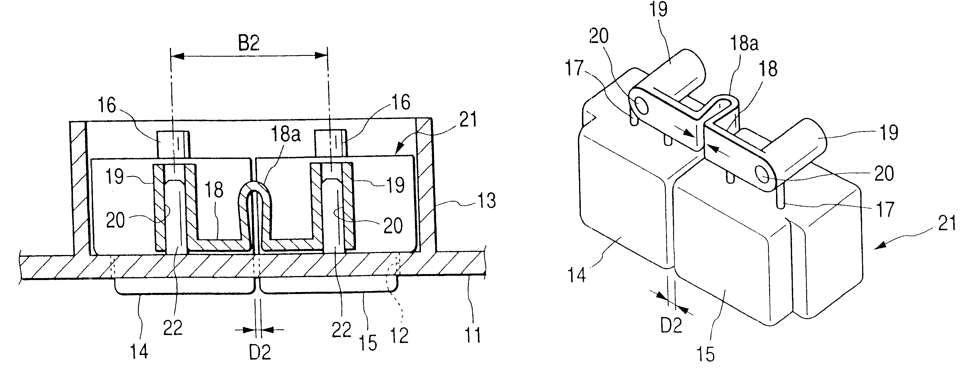
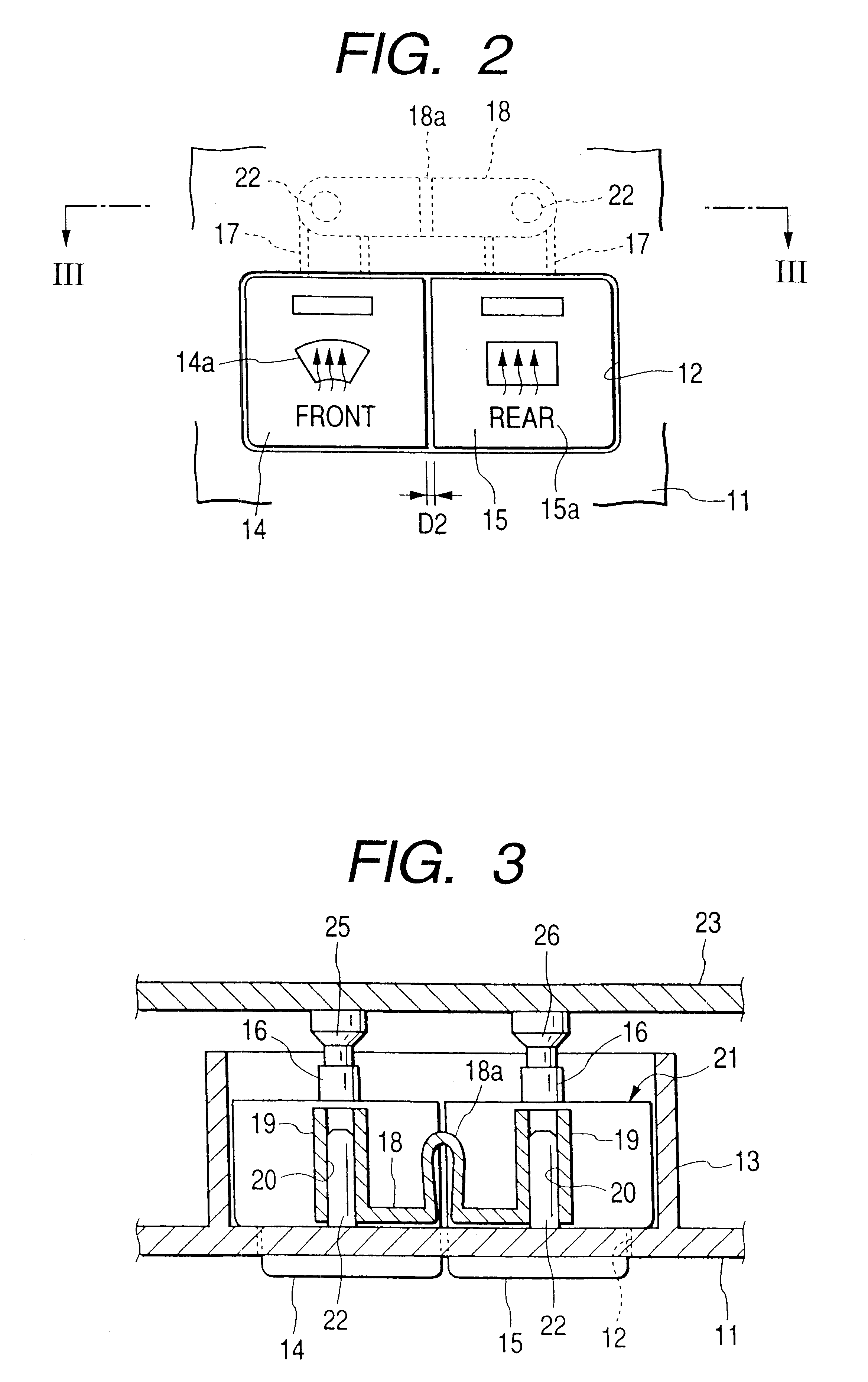
First, referring to FIGS. 2 and 3, a rectangular opening 12 elongated in a lateral direction is provided on a switch body 11 made of synthetic resin. Guide ribs 13 are formed being positioned on the reverse of the rim portion of the opening 12. In the opening 12, a plurality of operation knobs 14, 15 (two knobs in this embodiment) made of synthetic resin are arranged side by side to be operatively depressed. The operation knob 14 on the left in FIG. 2 is to be used for defogging the front windshield of a vehicle, and the operation knob 15 is used for defogging the rear window of the vehicle. On the front of each of the operation knobs 14, 15, there are provided display portions 14a, 15a each corresponding to these uses.

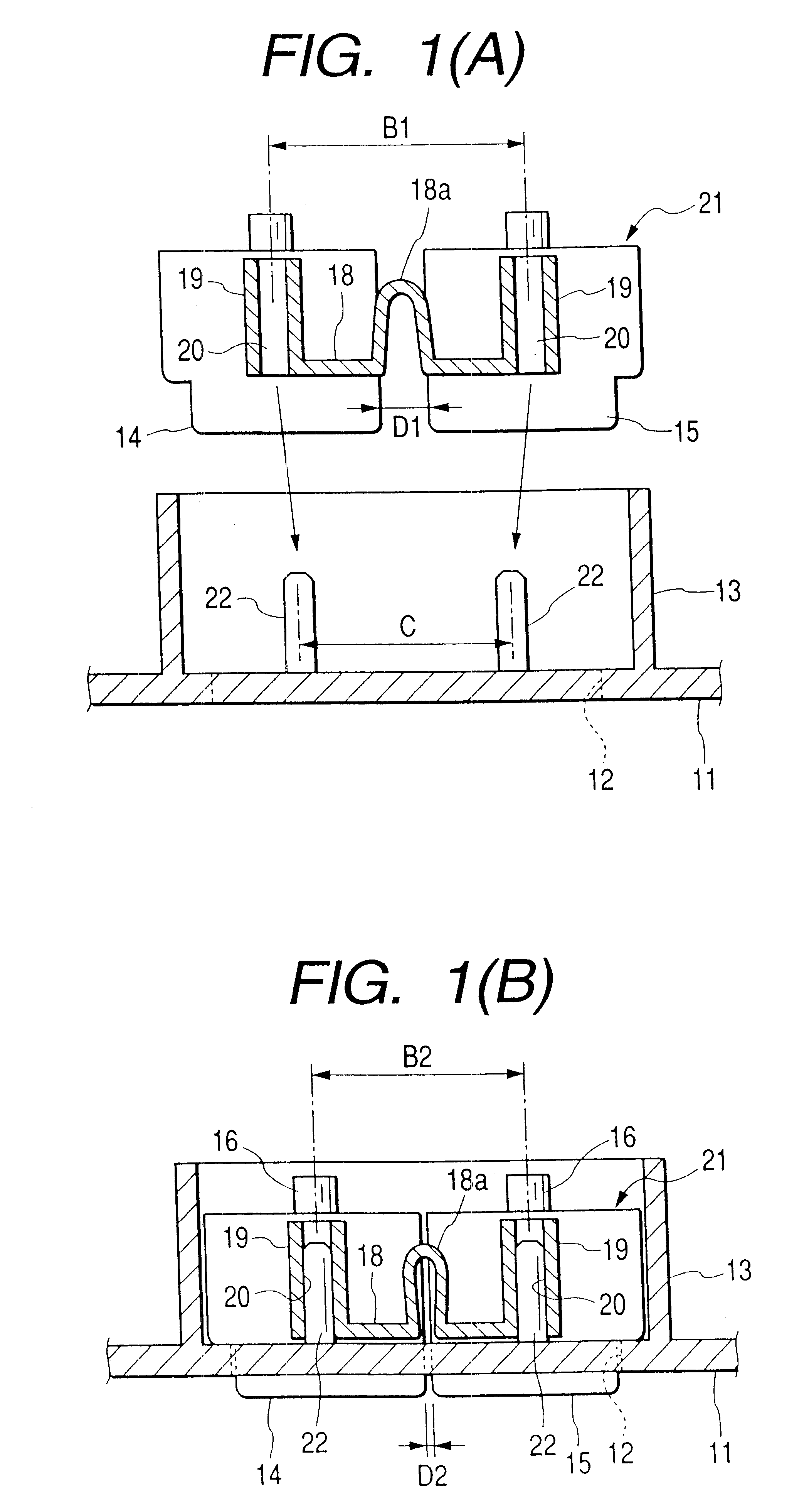
As shown in FIGS. 1 and 4, each aforementioned two operation knobs 14, 15 has a structure of a general knob holder and a knob integrated with each other. On the rear portion of ...


PUM


Abstract

Two adjacent operation knobs (14, 15) are formed integrally with each other via a coupling portion (18) On the coupling portion (18), there are formed a V-shaped gap variable portion (18a) and cylindrical portions (19) having positioning guide portions (20). There are provided pin-shaped positioning portions (22) on the switch body (11). To assemble the operation knobs (14, 15) to the switch body (11), each of the positioning guide portions (20) is mated with the positioning portions (22) and the front portion of the operation knobs (14, 15) is inserted into the opening (12). In cooperation with each of the positioning guide portions (20) and the positioning portions (22), the spacing dimension D2 between the operation knobs (14, 15) is narrowed, for example, down to 0.5 mm or less, and the spacing dimension is to be sustained.

Description

1. Technical FieldThe present invention relates to a switch device and the method for assembling the same. The switch device has a configuration in which a plurality of operation knobs are arranged side by side on a switch body to allow them to be pushed therein.2. Related ArtA configuration of a related switch device of this type will be explained with reference to FIGS. 5 and 6. A rectangular opening 1a elongated in a lateral direction is provided on a switch body 1. Guide ribs 1b are formed being positioned on the reverse side of the periphery of the opening 1a. In the opening 1a, two operation knobs 2, 3 are arranged side by side to be operatively depressed. The operation knobs 2, 3 comprise knob holders 2a, 3a and knobs 2b, 3b fitted in the front portion of the knob holders 2a, 3a, respectively. A wiring circuit board 4 is provided behind the operation knobs 2, 3. Push switches 5 corresponding to each of the operation knobs 2, 3 are arranged on he wiring circuit board 4.In the ...

Claims


Application Information

Patent Timeline
Patent Type & Authority Patents(United States)
IPC IPC(8): H01H3/12H01H3/02H01H13/14H01H13/70
CPCH01H3/12H01H2233/044H01H2221/026
Inventor OGAWA, SATOSHIAOKI, YOSHIYUKIISHIGURO, KAZUYOSHI
Owner KK TOKAI RIKA DENKI SEISAKUSHO
Why Eureka
Try Eureka