Angular mounted optical connector adaptor frame

a technology of optical connectors and adaptor frames, which is applied in the direction of optical elements, coupling device connections, instruments, etc., can solve the problems of increasing the depth of the electrical cabinet or closet, increasing the cost and increasing the difficulty of manufacturing a panel with angular connection points

Inactive Publication Date: 2003-09-23
FCI AMERICAS TECH LLC
View PDF25 Cites 129 Cited by
  • Summary
  • Abstract
  • Description
  • Claims
  • Application Information

AI Technical Summary

Problems solved by technology

The manufacture of a panel with angular connection points however is more difficult and more costly than the manufacture of a simple flat panel.
In addition, the use of a panel with angled portions adds to the depth of the electrical cabinet or closet.

Method used


Image

  • Angular mounted optical connector adaptor frame
  • Angular mounted optical connector adaptor frame
  • Angular mounted optical connector adaptor frame

Examples


first embodiment

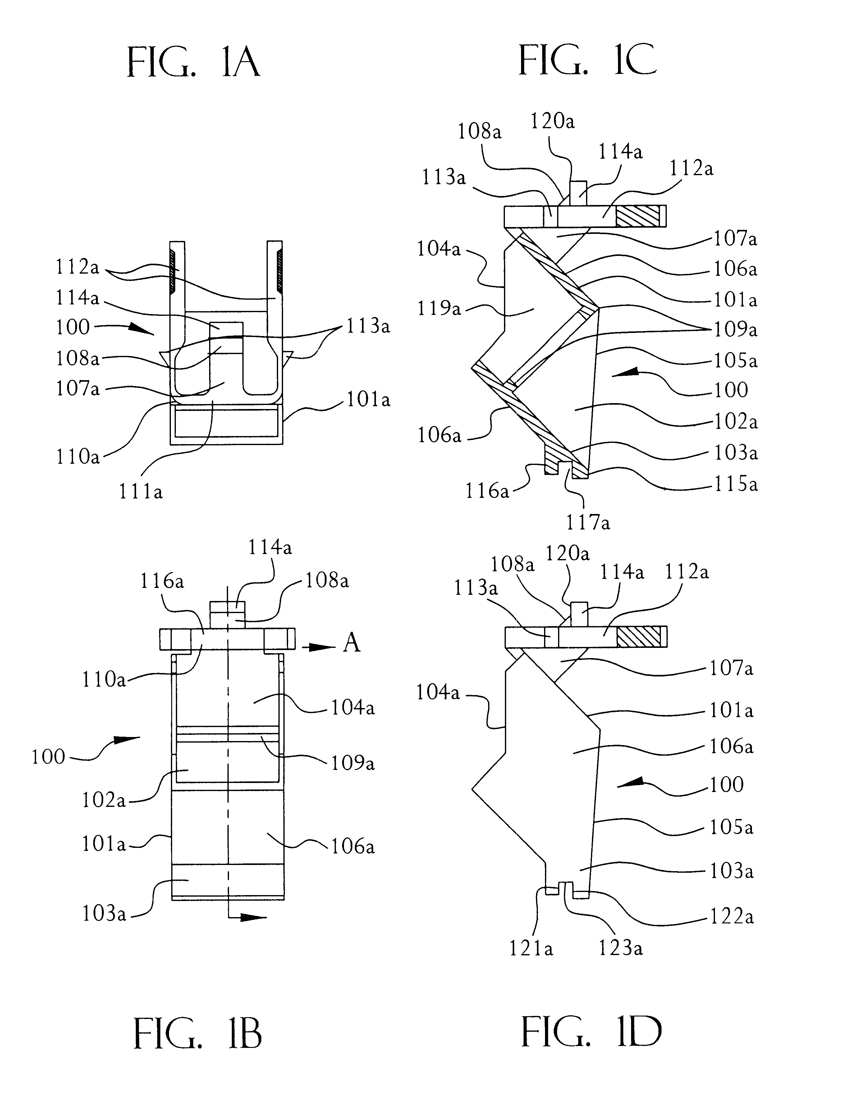
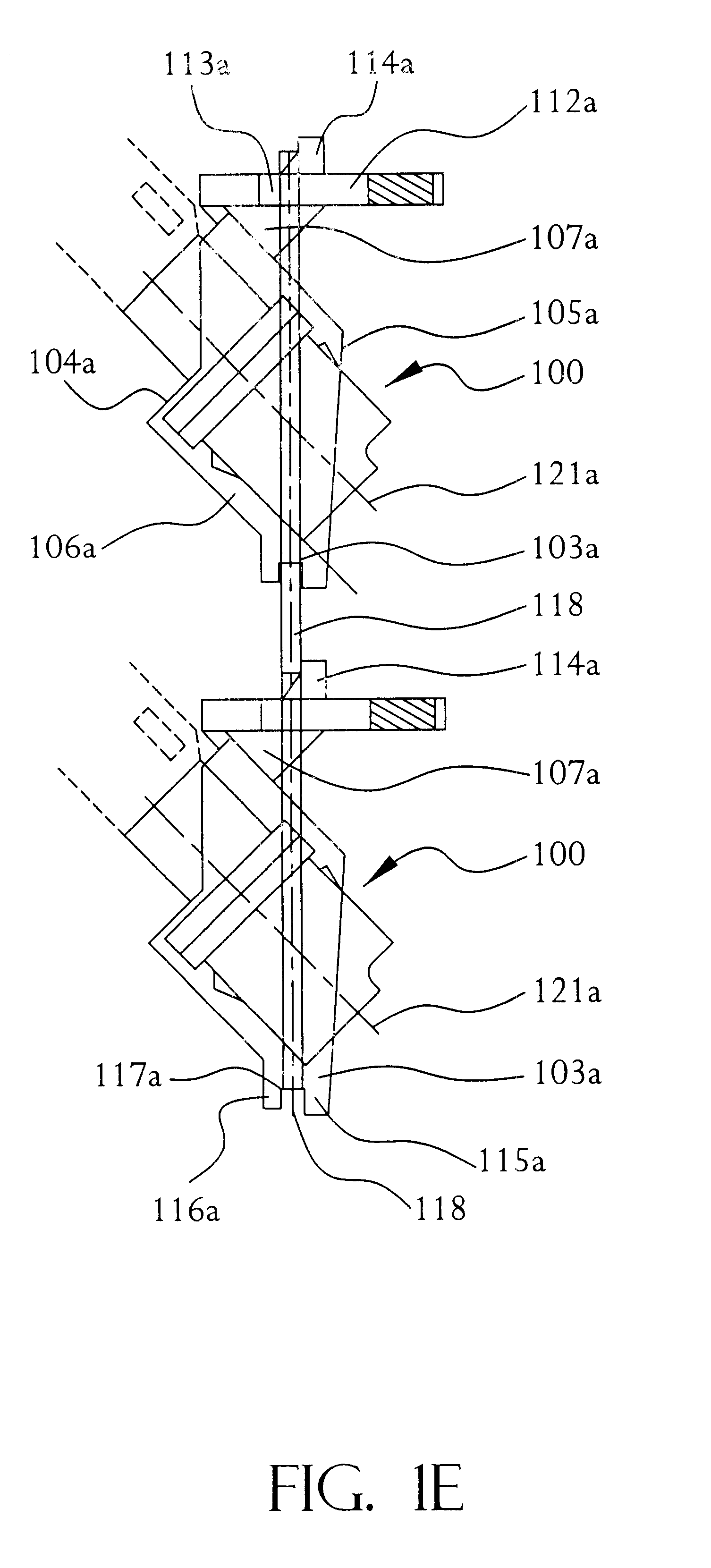
Throughout the following detailed description similar reference numbers refer to similar elements in all the Figs. of the drawings. Referring to FIGS. 1A-1D, several views of the invention are shown. Frame 100 is comprised of housing 101a, pivot 103a, stop 107a, and latch 110a. Frame 100 may comprise a single plastic injection-molded assembly, or an assembly of a number of components some or all of which may be plastic or other suitable material. Latch 110a should be formed of a material that is flexible but does not tends towards plastic deformation easily.

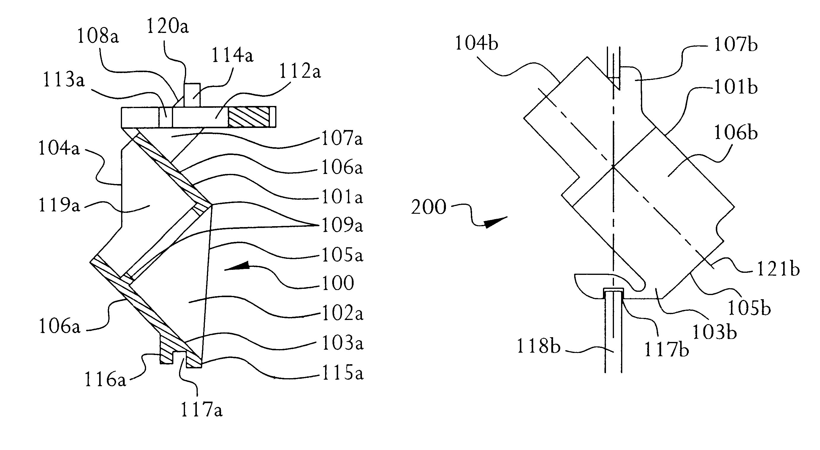
Housing 101a is open at front 104a and rear 105a to form central passageway 102a. The central axis 121a of central passageway 102a should form an oblique angle with the plane of the horizon. Forty-five degrees is optimal, but the oblique angle may be anywhere in the range of 15 to 75 degrees. Central passageway 102a receives and supports two cables joined by connectors or a connector-adaptor assembly when mounted to a flat panel ...

second embodiment

Referring now to FIGS. 2A-2D, several views of the invention are shown. Frame 200 is comprised of housing 101b, pivot 103b, and stop 107b. Frame 200 may comprise a single plastic injection-molded assembly, or an assembly of a number of components some or all of which may be plastic or other suitable material. The spring arm portion of pivot 103b should be formed of a material that is flexible but does not tends towards plastic deformation easily.

Housing 101b is open at front 104b and rear 105b to form a central passageway (not shown). The central axis 121b of the central passageway should form an oblique angle with the plane of the horizon. Forty-five degrees is optimal, but the oblique angle may be anywhere in the range of 15 to 75 degrees. The central passageway receives and supports four cables joined by two connector or connector adapter assemblies when mounted to a flat panel 118 as shown if FIG. 2D. It will be appreciated however that frame 200 is not limited in the number of ...

third embodiment

Referring now to FIGS. 3A-3D, several views of the invention are shown. Frame 300 is comprised of first housing 301 and second housing 308. First housing 301 is comprised of base 302, side walls 303, and front 304. First housing front 304 and base 302 are open to first cavity 317 formed by first housing side walls 303. A rectangular ridge 306 protrudes from one of the first housing side walls 303 along axis 315 which forms an oblique angle with the one of the first housing side walls 303. Forty-five degrees is optimal, but the oblique angle may be anywhere in the range of 15 to 75 degrees. A face of rectangular ridge 306 and the one of the first housing side walls 303 define mounting notch 307. It will be appreciated that ridge 306 need not be rectangular in shape but may take a variety of different forms.

Second housing 308 is comprised of base 309, side walls 310, and front 311. Second housing front 311 and base 309 are open to second cavity 318 formed by second housing side walls ...


PUM


Abstract

An angular mounted optical connector frame. The frame comprises a housing open at a front and a rear to form a central passageway along an axis at an oblique angle with respect to the horizon. A pivot is attached to the housing outer portion forward of the housing rear and has an axis of rotation parallel to the horizon but perpendicular to the axis of the central passageway. A stop having a first flat face is attached to the housing outer portion opposite the pivot and aft of the housing front. The frame may further comprise a latch formed by a base section attached to the housing outer portion opposite the pivot forward of the stop and two spring bars that extend in cantilever fashion around the stop and towards the housing rear. Each spring bar has a catch extending away from the stop mounted aft of the base section but forward of its first flat face. The frame may also comprise first and second housings, each having a base, side walls, and a front, joined at the bases thereof to form a single component. The bases and fronts of both the first and second housings are open to first and second cavities formed by the side walls of the first and second housings respectively. A first ridge protrudes from the first housing and defines a mounting notch between itself and the first housing side walls. A second ridge protrudes from the second housing and defines a recession therein for receiving a fastener.

Description

I. BACKGROUNDA. Field of the InventionThis invention relates generally to the field of panel connectors, and particularly to fiber optic panel connectors and methods of using the same.B. Description of the Related ArtIn electrical closets connections between transmission media are often made through connectors mounted on panels. Typically a panel includes a plate having an array of openings therein. A connector and / or connector adaptor is mounted in each of the openings. The types of connectors employed include copper modular connectors, coaxial connectors, optical fiber connectors, and the like. Often, space is at a premium on these panels. Efforts therefore have been made to maximize the number of connectors that may be employed per unit of panel surface space. One advance as a result of such efforts is the use of a flat panel with angled portions at the points where standard connectors are to be mounted. By placing the connectors at an angle with respect to the face of the panel ...

Claims


Application Information

Patent Timeline
Patent Type & Authority Patents(United States)
IPC IPC(8): G02B6/38H01R13/74
CPCG02B6/3897H01R13/741G02B6/3825
Inventor PETRILLO, NICOLAS PAUL
Owner FCI AMERICAS TECH LLC
Why Eureka
Try Eureka