Adjustable strain relief boot

a technology of strain relief and connector, which is applied in the direction of optics, instruments, optical light guides, etc., can solve the problems of optical signal passing through an optical fiber experiencing a power loss

Inactive Publication Date: 2003-10-21
STRATOS INT
View PDF13 Cites 147 Cited by
  • Summary
  • Abstract
  • Description
  • Claims
  • Application Information

AI Technical Summary

Problems solved by technology

An optical signal passing through an optical fiber can experience a power loss if the bend radius of the optical fiber is too great.

Method used


Image

  • Adjustable strain relief boot
  • Adjustable strain relief boot
  • Adjustable strain relief boot

Examples


Embodiment Construction

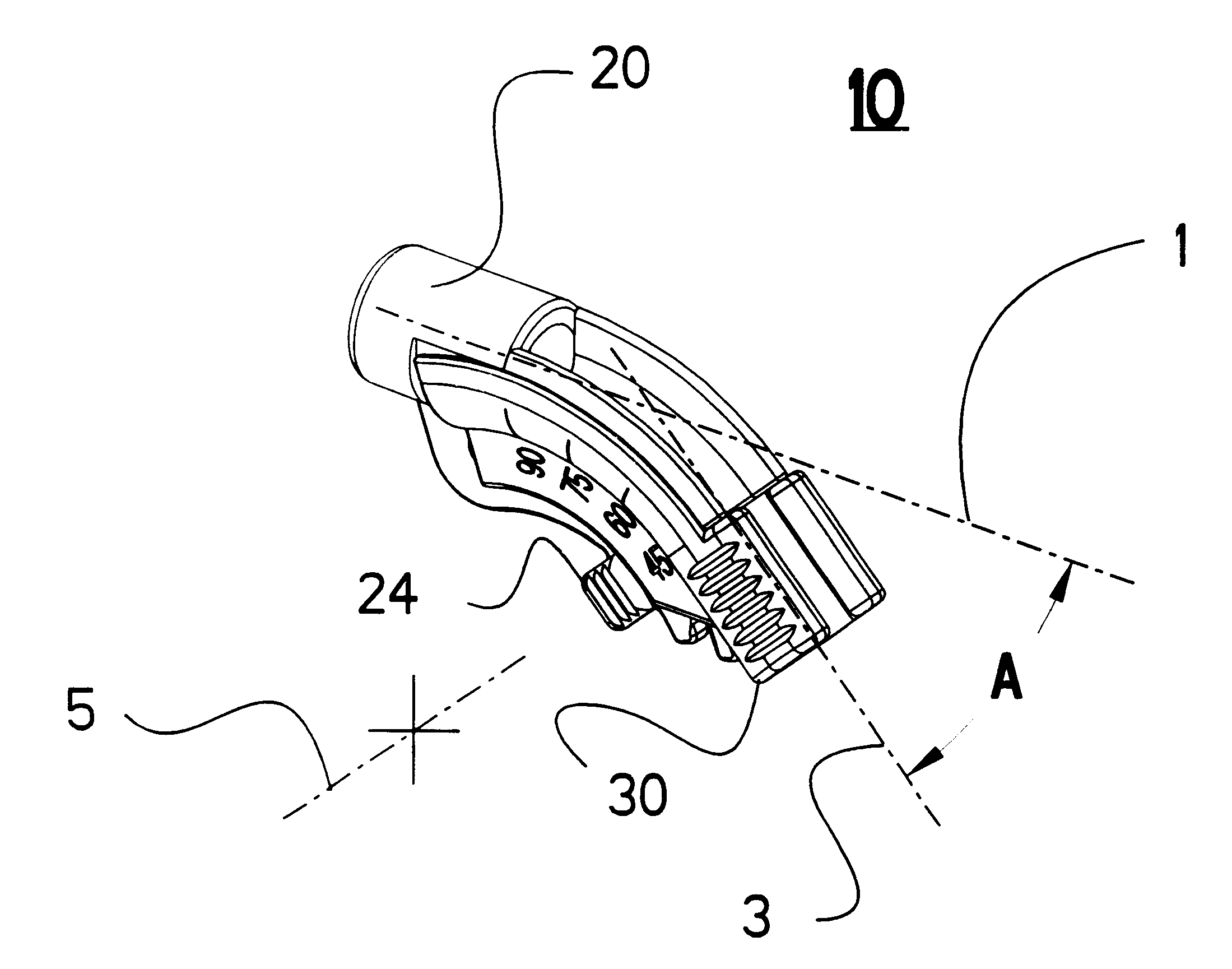
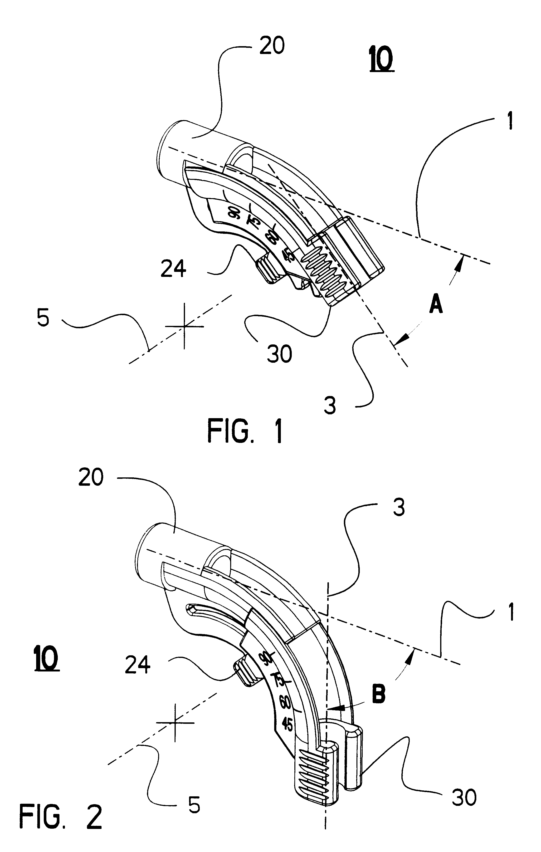
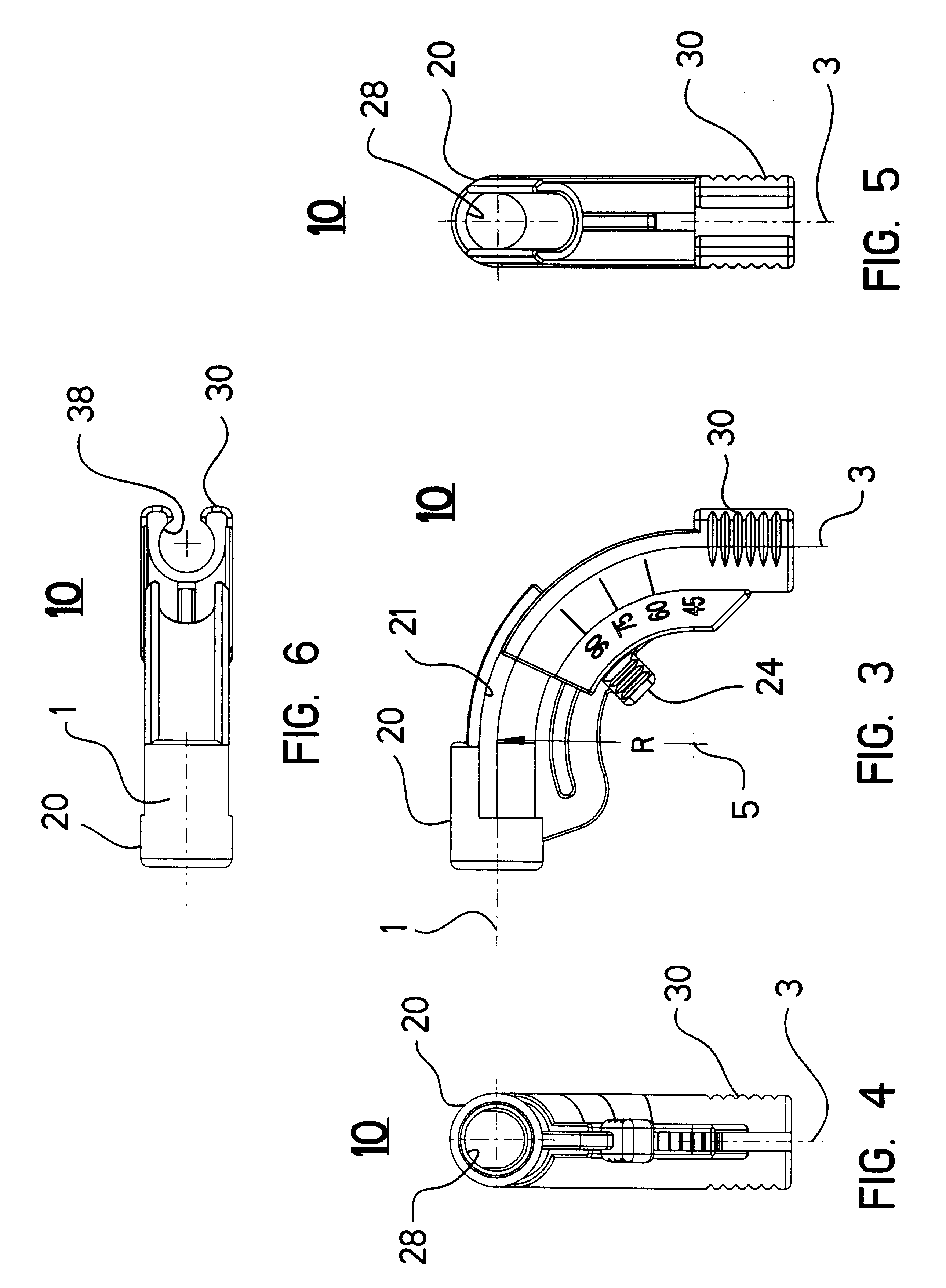
Referring now to the drawings, wherein like reference numerals designate identical or corresponding parts throughout the several views, and more particularly to FIGS. 1-11 thereof, an embodiment of the present invention is an adjustable strain relief boot 10.

FIG. 1 is a perspective view of the adjustable strain relief boot 10 adjusted to a fortyfive degree position. FIG. 1 shows the stationary portion 20 and the moving portion 30. The moving portion 30 is capable of pivoting about a pivot axis 5. When the adjustable strain relief boot 10 is adjusted to the forty-five degree position, the stationary portion fiber optic holder axis 1 is located forty-five degrees away from the moving portion fiber optic holder axis 3 and is identified by letter designator A. Furthermore, a release tab 24 of the stationary portion 20 is also shown as being aligned with a forty-five degree numerical indicator molded into the side of the moving portion 30. The length of a line normal to both the pivot ax...


PUM


Abstract

An adjustable strain relief boot includes a stationary portion and a moving portion slidably connected to the stationary portion. The adjustable strain relief boot is used to guide an optical fiber away from a connector of the optical fiber. In application, the stationary portion of the adjustable strain relief boot is press fitted onto to the connector. The adjustable strain relief boot provides for a predetermined, fixed angle of departure of the optical fiber away from the connector. The fixed angle of departure can be adjusted by the operator from a first position to a second position. The fixed angle of departure is adjustable between forty five and ninety degrees. In a locked position, the moving portion can not move relative to the stationary portion since actuator engagement teeth of an actuator arm of the stationary portion engage teeth of the moving portion. In an unlocked position, a force is applied to a release tab of the actuator arm of the stationary portion so as to disengage the actuator engagement teeth of the stationary from the teeth of the moving portion so as to allow the moving portion to move relative to the stationary portion. Due to the resiliency of the actuator arm of the stationary portion, when the force applied to the release tab is removed, the actuator arm tends to move towards its undeflected position thus engaging the actuator engagement teeth with the teeth of the moving portion.

Description

1. Field of the InventionThe present invention relates to a strain relief boot for a connector. The invention more particularly concerns a strain relief boot which is adjustable and where the adjustable strain relief boot is used in combination with an optical connector having an optical fiber.2. Discussion of the BackgroundThe application of fiber optics to the telecommunication and data storage industries is expanding ever day. Fiber optics enables the high-speed transmission of communications and data. Connectors for optical fibers can be found in the back of instrumentation, telecommunication, routing, and switching cabinets. These cabinets accept a large number of fiber optic connectors. The optical fibers project away from the connector and tend to bend toward the ground due to the effect of gravity or the optical fibers are bent in a different direction due to an externally applied force. An optical signal passing through an optical fiber can experience a power loss if the be...

Claims


Application Information

Patent Timeline
Patent Type & Authority Patents(United States)
IPC IPC(8): G02B6/38
CPCG02B6/3887G02B6/38875
Inventor WALDRON, MARK R.SIMMONS, THOM
Owner STRATOS INT
Why Eureka
Try Eureka