Central strength member with reduced radial stiffness

a technology of central strength and radial stiffness, applied in the direction of optics, fibre mechanical structures, instruments, etc., can solve the problems of significant attenuation problems, damage to buffer tubes, and prone to severe damage to cable configurations designed according to traditional standards

Inactive Publication Date: 2003-11-25
ALCATEL LUCENT SAS
View PDF11 Cites 31 Cited by
  • Summary
  • Abstract
  • Description
  • Claims
  • Application Information

AI Technical Summary

Problems solved by technology

It has recently been observed that cable configurations designed according to traditional standards are prone to suffer severe damage during installation and sheave testing.
In many cases, the buffer tubes tear open, which allows for fiber bundles to protrude out from the buffer tubes, resulting in significant attenuation problems.
A main cause of the damage to the buffer tubes is due to a force exerted onto the buffer tubes by the CSM.

Method used


Image

  • Central strength member with reduced radial stiffness
  • Central strength member with reduced radial stiffness
  • Central strength member with reduced radial stiffness

Examples


Embodiment Construction

The present invention will be explained in further detail by making reference to the accompanying drawings, which do not limit the scope of the invention in any way.

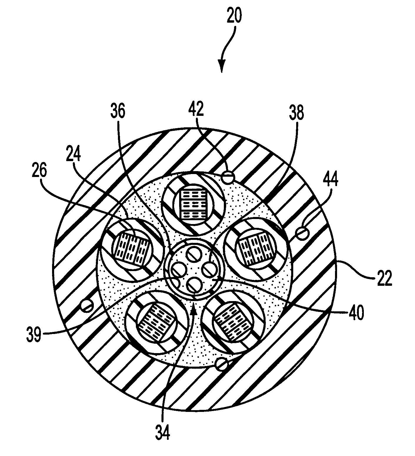
With reference to FIG. 3, an optical fiber cable configuration 20 is shown having a tubular outer jacket 22. The outer jacket 22 is used to house a plurality of buffer tubes 24. The buffer tubes 24 contain optical fiber ribbons 26. As one skilled in the art will appreciate, the buffer tubes 24 may also contain other formations of optical fibers. In this embodiment, five buffer tubes are shown; however, the number of buffer tubes 24 may be increased or decreased depending on the application.

According to the present invention, a CSM 28 is positioned concentrically with respect to the outer jacket 22. The CSM 28 includes a tube or strength tube 30, which has a hollowed-out center portion. The tube 30 may be made from a plastic, for example, polyethylene, polypropylene, PBT, PVC and plastic-based composite materials. A large...


PUM


Abstract

An optical fiber cable configuration having a central strength member. The central strength member includes a hollow tube. One or more strength rods are disposed along or within the tube. To avoid water penetration, the tube is filled with a gel or water-absorbing powder, which provides a water barrier.

Description

1. Field of the InventionThe present invention generally relate to the field of fiber optic cables and, in particular, the present invention is directed to a fiber optic cable configuration having a central strength member with reduced radial stiffness.2. Discussion of Related ArtOptical fibers are very small diameter glass strands that are capable of transmitting an optical signal over great distances, at high speeds, and with extremely low signal loss as compared to standard wire or cable networks. Optical fiber has found increasingly widespread application and currently constitutes the backbone of the worldwide telecommunication network. Because of this development, there has been a growing need for better quality optical fiber cables with a decrease in production time and costs, while ensuring adequate robustness for continued operation in increasingly harsh conditions. Proper signal transmission requires structurally sound jackets and protective covers to protect the optical fi...

Claims


Application Information

Patent Timeline
Patent Type & Authority Patents(United States)
IPC IPC(8): G02B6/44
CPCG02B6/4434G02B6/4411G02B6/4494G02B6/44384
Inventor NECHITAILO, NICHOLAS V.RATTAZZI, DEAN J.
Owner ALCATEL LUCENT SAS
Why Eureka
Try Eureka