Multiple chemical product eductive dispenser

a technology which is applied in the field of eductor device and chemical product selection, can solve the problems of inability to efficiently, affecting the efficiency of purging system, and reducing the accuracy of volume and timing of fluid mixing,

Inactive Publication Date: 2003-12-02
DELAWARE CAPITAL FORMATION INC
View PDF28 Cites 42 Cited by
  • Summary
  • Abstract
  • Description
  • Claims
  • Application Information

AI Technical Summary

Problems solved by technology

One problem associated with selector valves of this type is the ability to efficiently change over from one selected input chemical fluid to another.
Purging the system is very detrimental in that it requires delays in the operation and diminishes the accuracy of the volume and timing of the mixing of the fluids.
Because of the distance and the geometry of the path the selected fluid must travel within the selector valve system, the system may contain a significant amount of residual chemical after the user has selected a new inlet port, thereby requiring the user to spend time purging the line.
Specifically, the cause of turbulent flow in the selected fluid flow path is commonly stagnation points or blind spots which are typically found at the juncture between mating components.
These areas create turbulent flow of the fluid through the selector valve and minimize the ability to effectively purge the valve and flush the residual chemicals.
Additionally, turbulent flow through the selector valve retards the fluid flow and requires greater pressures and timing problems for the selected input fluid sources and responsiveness of the selector valve and connected system components.
While many applications benefitted from the relatively small amount of carry-over, other applications were not suitable.
For example, selecting a particular mixture requires positioning one or more of several different levers increases the opportunity for human error.

Method used


Image

  • Multiple chemical product eductive dispenser
  • Multiple chemical product eductive dispenser
  • Multiple chemical product eductive dispenser

Examples


first embodiment

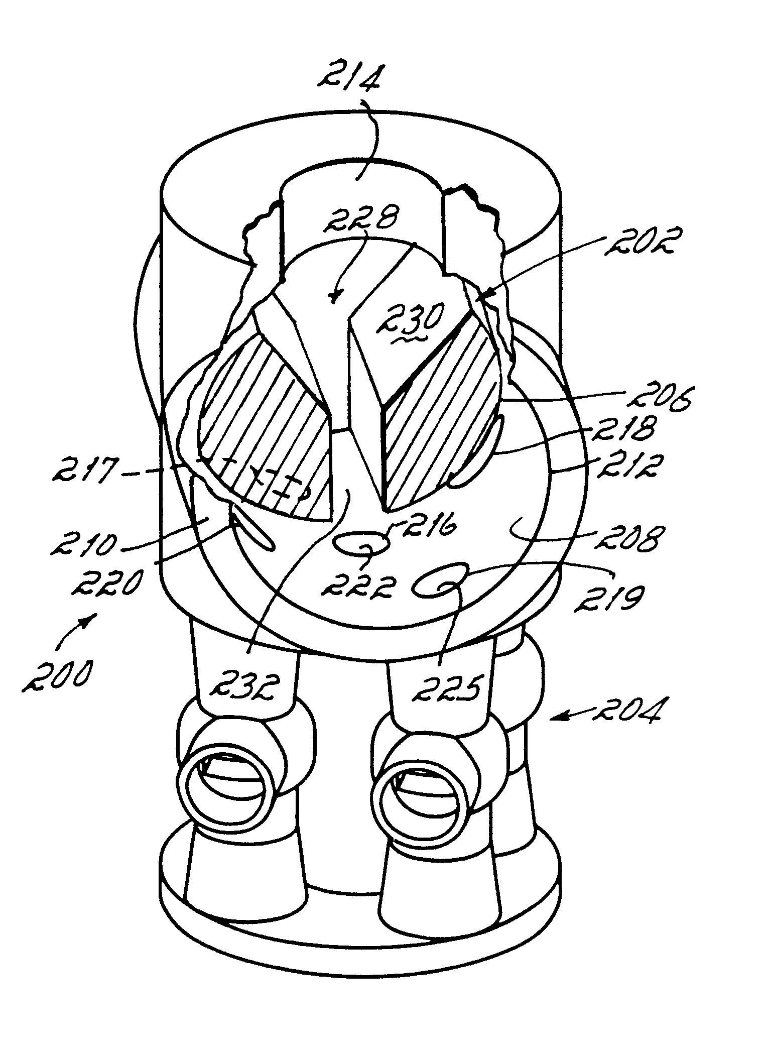
FIGS. 3-5 depict a selector disk device 60 for the dispenser 30 of FIG. 2. In particular, the device 60 is integrally formed from separately molded and attached components of a selector body 62, an eductor body 64, and an outlet 66. Between the selector and eductor bodies 62, 64, a selector disk 68 and selector seal 70 are contained.

With particular reference to FIG. 3, the selector disk 68 is rotated by an externally exposed lever 72 for angularly positioning a disk orifice 74 in the selector disk 68 to one of a plurality of sealed orifices 76, 77, 79 under the selector disk 68, which in turn are respectively registered to one of a plurality of inlets 82-84 in the eductor body 64. The eductor body 64 includes a plurality of fluid channels 88-90 that correspond to and include the inlets 82-84. In the illustrative depiction, there is no fourth inlet and no corresponding fluid channel. This allows the selector disk 68 to be positioned to an OFF position at a blind position.

With particu...

second embodiment

FIGS. 6-8 depict a device 120 for the dispenser 30 of FIG. 2 that employs a concentric disk selection member 122 for diverting motive fluid. In the illustrative depiction, an eductor body 124 is similar to the previously described eductor body of FIGS. 3-5, other than having four fluid channels 126-129 rather than the previously described three. Thus, the device 120 does not have an OFF position. Instead, the device 120 has a selection member 122 capable of simultaneously selecting one, two, three or four fluid channels 126-129. Thereby, the device 120 is capable of mixing fluids to achieve different dilution ratios of the same chemical fluid or to simultaneously combine two or more chemical fluids with a motive fluid.

The combinations are selectable by radially elongated inlets 132-135 to the respective fluid channels 126-129. Then, an outer concentric selector disk 138, rotatably contained within the device 120, has an angularly elongated orifice 140 that can be angularly positione...

third embodiment

FIGS. 9, 10 depict a device 150 for the dispenser 30 of FIG. 2 that uses push button selection member 152 for diverting motive fluid. In the illustrative depiction, an eductor body 154 is similar to the previously described eductor bodies, except having a fluid channel 156 that is surrounded by four other fluid channels 157-160. A selector body 162 includes a motive fluid passage 164 that separates into vertically elongated inlets 166-170, each corresponding and vertically aligned with an assigned fluid channel 156-160. The selection member 152 traverses a plane that intersects or blocks each inlet 166-170. In particular, the selection member 152 includes a plurality of selection spools or lands 172-176, each traversing within a spool cavity 178-182, as shown in FIG. 10. Each land 172-176 includes a recessed portion 184-188 registered to align with the respective inlet 166-170 as the spool 172-176 traverses through the respective spool cavity 178-182.


PUM


Abstract

A dispenser selectively mixes one or more chemical fluids into a motive fluid such as water by using diverting motive fluid to one or more channels formed in an eductor body, at least one of the channels being an eductor. When the motive fluid passes through the eductor, a selected chemical fluid is eductively drawn into the venturi of the eductor, producing a mixed fluid having a desired total flow rate and dilution ratio. Additional dilution ratios, flow rates, and chemical fluids are selectable by diverting motive fluid to another channel or combinations of channels. Carry-over of chemical fluid between dispensing is avoided by diverting the motive fluid rather than by diverting the concentrated chemical fluid.

Description

1. Field of the InventionThis invention relates to dispensers and more particularly to a chemical product selection and venturi eductor device for selectively dispensing and mixing, at a corresponding dilution ratio and total fluid flow rate, one of a plurality of fluids with another fluid.2. Prior ArtSelector valves typically allow an operator to select and dispense one particular chemical fluid at a time, while closing off access to all of the other fluid sources available for selection. One such prior selector valve typically includes a static body having several inlet ports and one outlet port and a rotatable valve core with passages to allow selective connection of a selected inlet port with the outlet port. Sealing of the non-selected inlet ports is provided by a spring loaded, O-ring sealed plunger carried in the rotatable core and bearing against the face of the static body. While selector valves of this type allow for selective connection and dispensing of a plurality of fl...

Claims


Application Information

Patent Timeline
Patent Type & Authority Patents(United States)
IPC IPC(8): B01F15/02B01F5/04
CPCB01F5/0413B01F15/0201B01F5/043Y10T137/87595Y10T137/0318Y10T137/87281Y10T137/87346Y10T137/87619Y10T137/86871B01F25/312B01F25/31243B01F35/71
Inventor SAND, WILLIAM F.DALHART, MARK D.
Owner DELAWARE CAPITAL FORMATION INC
Why Eureka
Try Eureka