Hair clip

Inactive Publication Date: 2003-12-30
CHOU KUO HUA
View PDF6 Cites 35 Cited by
  • Summary
  • Abstract
  • Description
  • Claims
  • Application Information

AI Technical Summary

Benefits of technology

Present invention aims to simplify hair cli

Problems solved by technology

As the contact area between hairs (5) and hair clip is limited, the hair clip may fall off very easily.
In addition, the production of middle cli

Method used


Image

  • Hair clip
  • Hair clip
  • Hair clip

Examples


Embodiment Construction

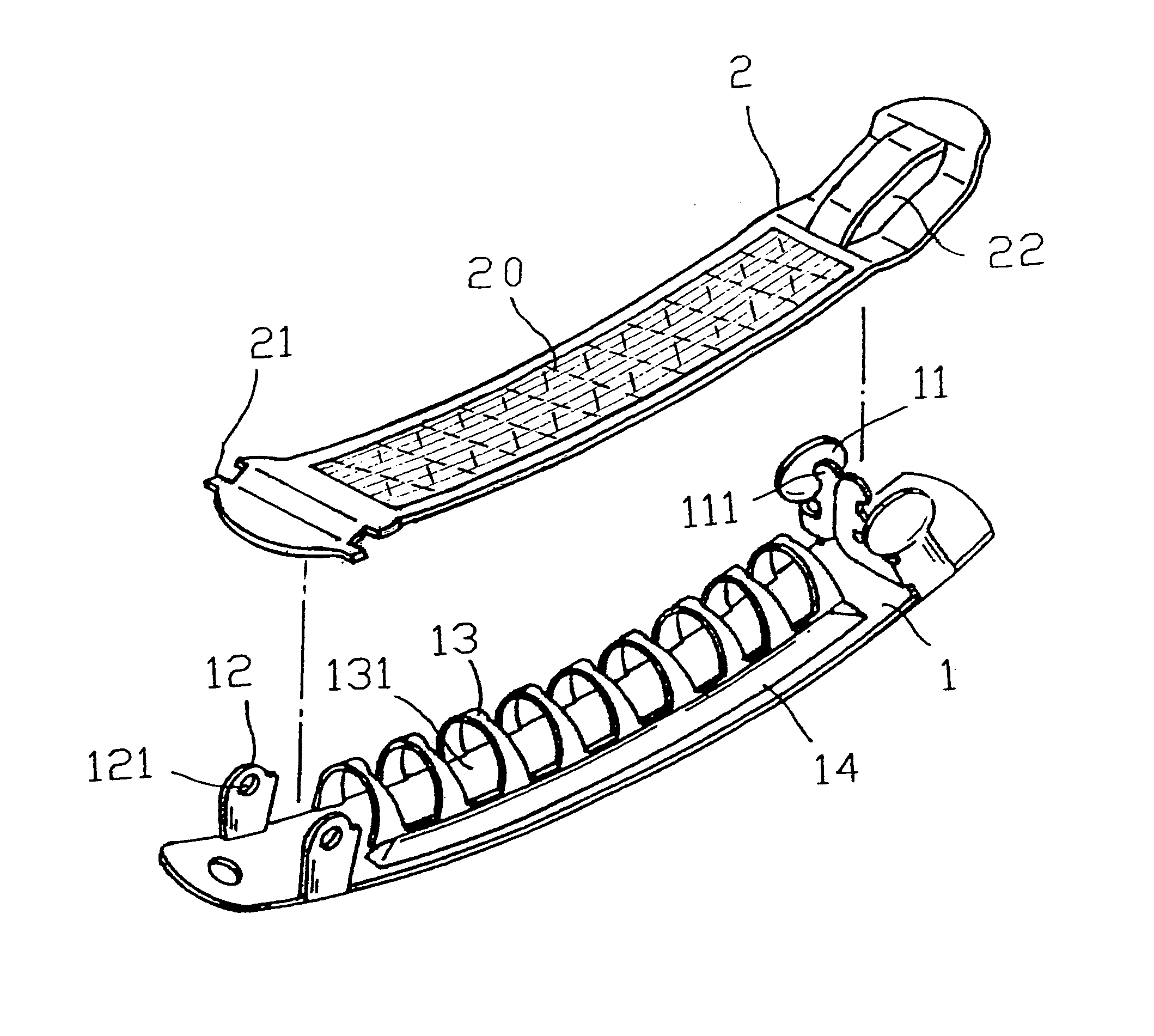
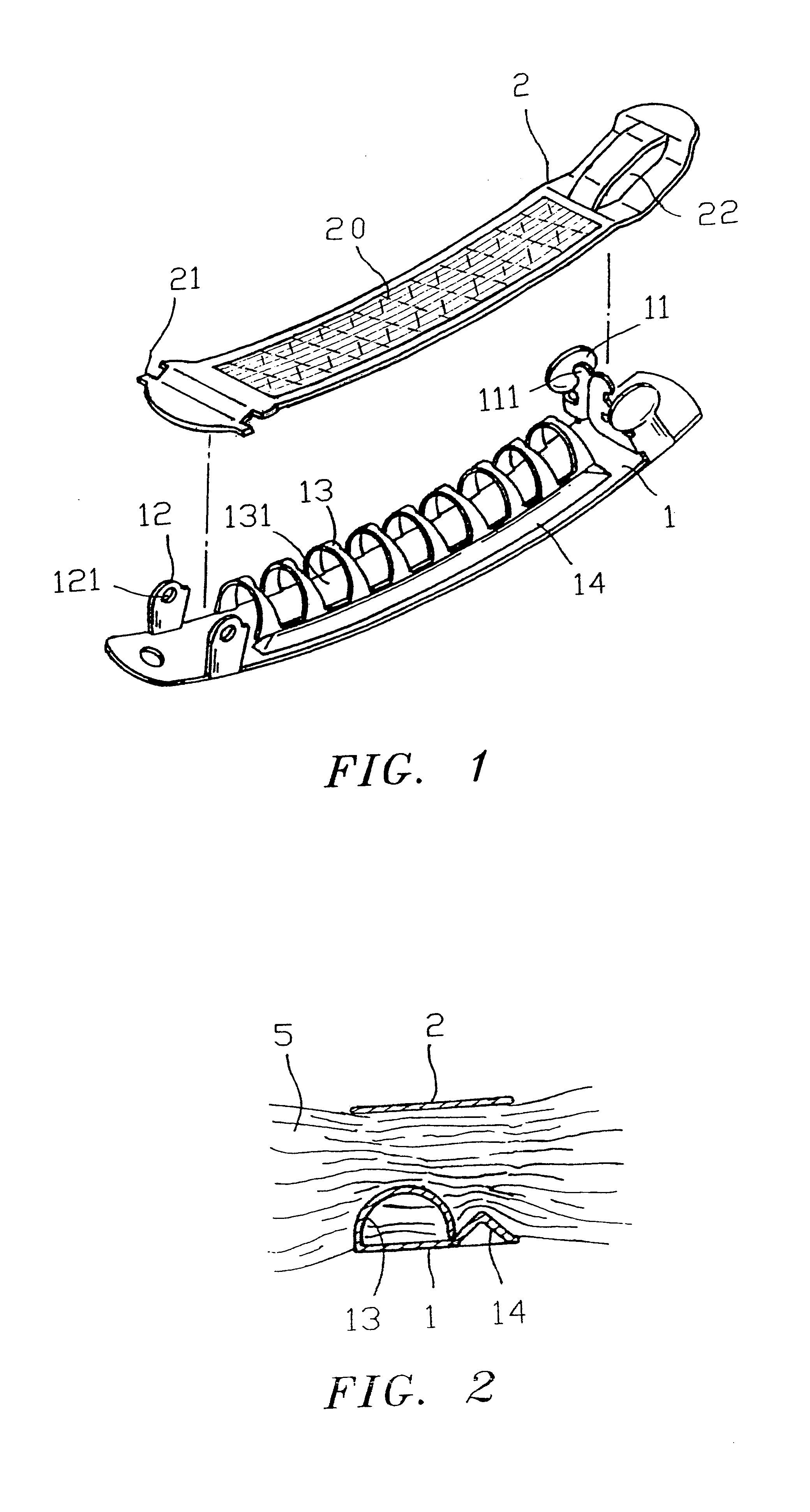
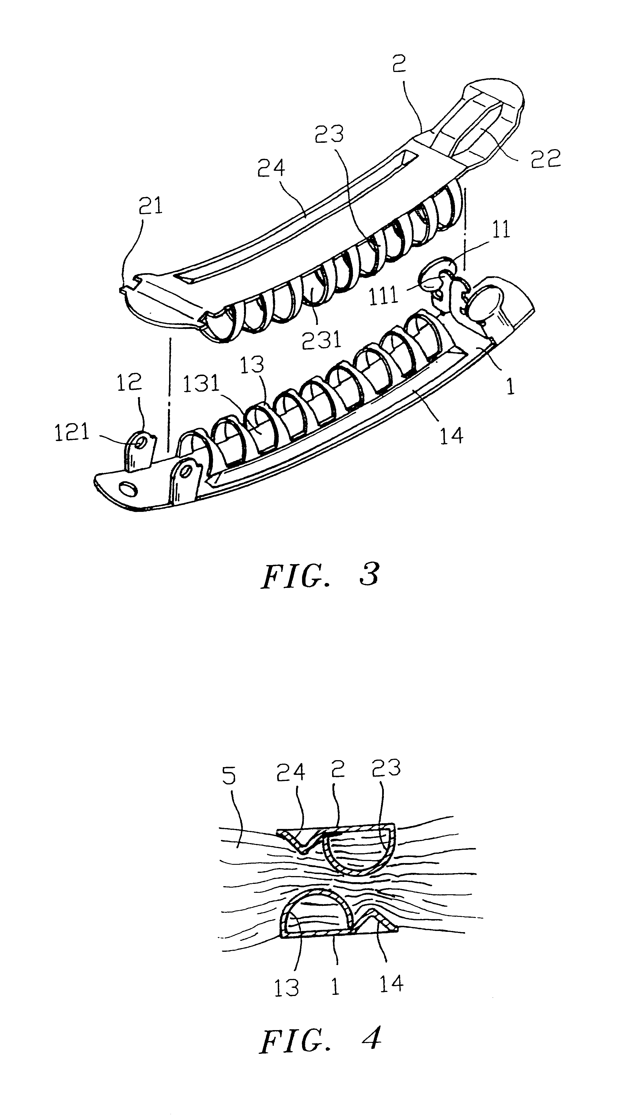
FIG. 1 illustrates 1.sup.st application of present invention. Said application comprises base plate (1), wherein two corresponding pressure strips (11) are equipped at one lateral end. Each of said pressure strips (11) further equip with an inwardly extended hook. Both sides of another end comprise pivot plates (12), each of which further encompasses a coupling hole (121). One lateral end of upper clip plate (2) equips with a pivot pin (21) on both sides. The attachment of pivot pin (21) to coupling hole (121) connects upper clip plate (2) to base plate (1). Other end of upper clip plate (2) can open and close freely. Such end equips with a buckling hole (22) to buckle hooks (111) of base plate (1).

Multiple equally spaced curved strips (13) (hair allocation mechanisms) are equipped on one side of base plate (1) which further forms multiple rooms (131). A support strip (14) is equipped on other side of base plate (1). One end of curved strips (13) reaches against the inner side of su...


PUM


Abstract

Present invention relates to a hair clip that mainly comprises: a base plate and an upper clip plate. Multiple equally spaced curved strips are equipped along the length of base plate. Such curved strips further form multiple rooms on base plate. Application of present invention allows hairs to be distributed evenly within the rooms and clips hairs firmly between upper clip plate and base plate to prevent hairs from distortion and damage. In addition, by eliminating middle clip plate the production cost is lowered.

Description

Present invention particularly relates to a hair clip which provides even hair Distribution in all directions. Such hair clip will not fall off from hair easily and also provides protection against hair damage,Common hair clip (refer to FIGS. 13 to 15) comprises at least base plate (6), upper clip plate (7), middle clip plate (8), and other components. As said hair clip clips, curved pressure strip (71) at the center of upper clip plate (7) tightly presses hairs (5) into hallow center (81) of middle clip plate (8) to achieve solid clipping effect. Regardless of the amount of hairs (5) being clipped, common hair clip fails to allocate hairs (5) evenly for the following reasons:1. The clipping space between upper clip plate (7) and middle clip plate (8) is very limited at the center but more spacious at both ends. Consequently more hairs (5) are allocated at both ends.2. The curvature of curved pressure strips (71) of both middle clip plate (8) and upper clip plate (7) are in opposite...

Claims


Application Information

Patent Timeline
IPC IPC(8): A45D8/24A45D8/00
CPCA45D8/24
Inventor CHOU, KUO HUA
Owner CHOU KUO HUA
Why Eureka
Try Eureka