Combination flashlight and candle lantern

a technology of candle lanterns and flashlights, applied in the field of candle lanterns, can solve the problems of difficult light in the dark, battery to be completely discharged, battery gradually losing its charge when not used, etc., and achieve the effect of preventing inadvertent activation and low profil

Inactive Publication Date: 2004-02-03
INDAL REVOLUTION
View PDF18 Cites 10 Cited by
  • Summary
  • Abstract
  • Description
  • Claims
  • Application Information

AI Technical Summary

Problems solved by technology

Because of the difficulty in determining the amount of time a set of batteries will continue producing energy, extra batteries are usually carried by the user.
Also, because of the batteries' relatively short life, they must be used with discretion.
Unfortunately, the batteries gradually lose their charge when not used.
Another problem is that their switches can inadvertently be turned-on when carried in a backpack thus causing the batteries to be completely discharged.
One drawback with candle lanterns, however, is that they can be difficult to light in the dark and in windy conditions.
In order to ignite the wick, the candle is often tilted to one side which causes a small amount of hot liquid wax to accumulate on the top of the candle and spill onto the user.

Method used


Image

  • Combination flashlight and candle lantern
  • Combination flashlight and candle lantern
  • Combination flashlight and candle lantern

Examples


Embodiment Construction

)

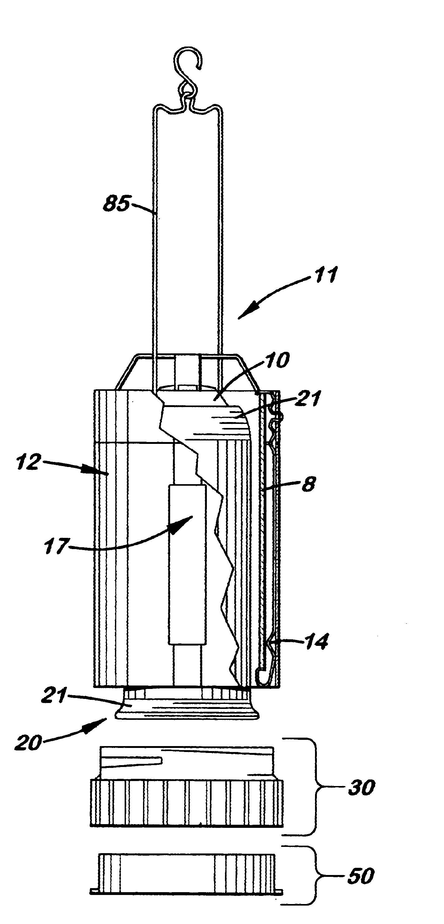
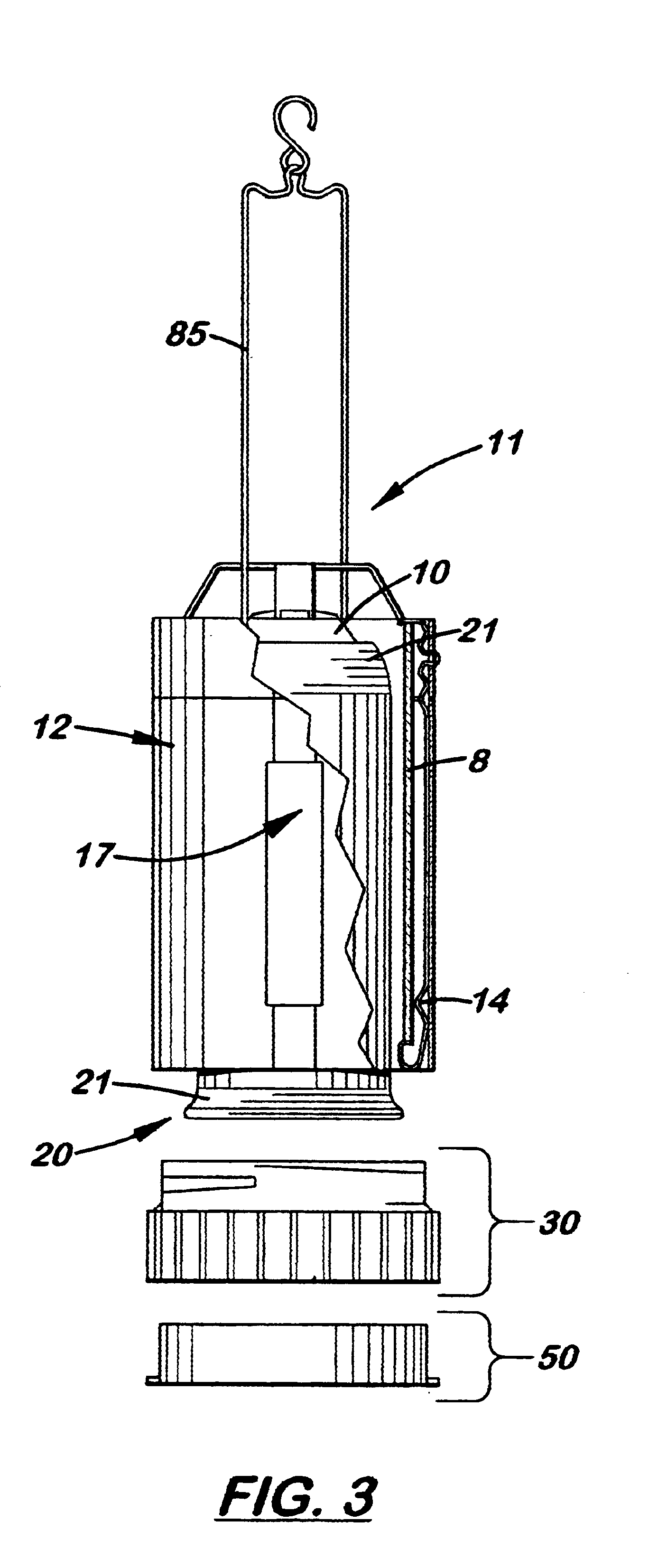
Referring to the accompanying FIG. 3, there is shown and described a combination flashlight / candle lantern 11 composed of the upper metal cover 12, a modified lower base 30, a candle holding assembly 51, an elongated candle 10 and a cylindrical lens 8. The modified lower base 30, shown more clearly in FIGS. 4-7, is cylindrical-shaped with upward extending outer sidewall 32 that include grooves 33 formed on its outer surface that connect to detents 14 formed near the lower edge of the upper cover 12. Formed inside the modified lower base 30 is a candle receiving upper cavity 35 designed to connect to a candle holding assembly 51 that holds an elongated candle 10 in an upright, perpendicularly aligned position.

The candle holding assembly 20 includes a candle tube 21 selectively mounted on a candle platform 36 formed inside the modified lower base 30. Disposed inside the candle tube 21 is a longitudinally aligned spring similar to the spring 15 used in the candle lantern 5 found in th...


PUM


Abstract

A combination flashlight / candle lantern with a modified lower base designed to be used with the standard, metallic cover on a candle lantern. The modified lower base has an upper neck designed to selectively attach to the metallic cover. The modified lower base also includes an upward extending cavity and a transversely aligned candle platform designed to receive a tube candle. Formed on the opposite side of the candle platform is a downward extending lower cavity designed to receive a low profile flashlight assembly. The flashlight assembly includes a cylindrical-shaped housing designed to partially extend into the lower base. Located centrally on the housing is a longitudinally extending LED electrically connected to two side-by-side watch batteries. Attached over the lower opening on the housing is a combination lens / switch which, when rotated, controls operation of the LED. The flashlight assembly may also include a bail located on the base member opposite the combination lens / switch. The bail may be disposed in a concealed manner when the flashlight assembly is attached to the lower base, or may allow the separated flashlight assembly to be independently supported from a hook or aimed on a flat surface.

Description

1. Field of the InventionThis invention pertains to candle lanterns, and, more particularly, to candle lanterns with flashlight components.2. Description of the Related ArtBattery-powered flashlights and lanterns have been used for many years for general-purpose recreational lighting. Because of the difficulty in determining the amount of time a set of batteries will continue producing energy, extra batteries are usually carried by the user. Also, because of the batteries' relatively short life, they must be used with discretion. Unfortunately, the batteries gradually lose their charge when not used. Therefore, most users remove them from their backpacks when the backpacks are placed in storage. Another problem is that their switches can inadvertently be turned-on when carried in a backpack thus causing the batteries to be completely discharged.Candle lanterns, such as those disclosed in U.S. Pat. Nos. 4,566,055 and 5,688,040 are very popular with all types of recreational users. Ca...

Claims


Application Information

Patent Timeline
Patent Type & Authority Patents(United States)
IPC IPC(8): F21V35/00F21L4/00F21L19/00F21V23/04
CPCF21L4/005F21L19/00F21V35/00F21V23/0414F21Y2101/02F21Y2115/10
Inventor KLEES, GARRY W.
Owner INDAL REVOLUTION
Why Eureka
Try Eureka