
Mounting bracket

a technology for mounting brackets and brackets, which is applied in the direction of curtain suspension devices, building scaffolds, domestic objects, etc., and can solve problems such as access and alignment problems

Inactive Publication Date: 2004-03-23
LIGERTWOOD PETER
View PDF19 Cites 148 Cited by
  • Summary
  • Abstract
  • Description
  • Claims
  • Application Information

AI Technical Summary

Benefits of technology

"The present invention provides a mounting unit for attaching a working unit, such as a video projector, to a mounting surface. The mounting unit includes an anchorage for attachment to the surface, a beam, a carrier with a holding plate and a mounting plate, and a pivot mechanism that allows the mounting plate to pivot about multiple axes. The carrier can also rotate about an axis. The mounting plate can be rotated about an axis parallel to the holding plate. The beam is telescopic and variable in length to provide maximum and minimum separation of the attachment points. The mounting unit can be used with a variety of surfaces, such as horizontal, vertical, or surfaces between horizontal and vertical. The bracket is partially dismantled in the figures for illustration purposes. The technical effects of the invention include improved stability and flexibility in mounting a video projector, as well as compatibility with a variety of surfaces."

Problems solved by technology

However the provision of a high mounting bracket can cause access and alignment problems when a projector is to be mounted by means of the bracket.

Method used


Image

  • Mounting bracket
  • Mounting bracket
  • Mounting bracket

Examples


Embodiment Construction

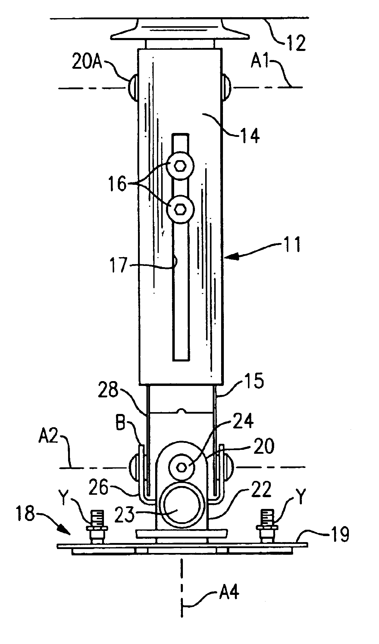
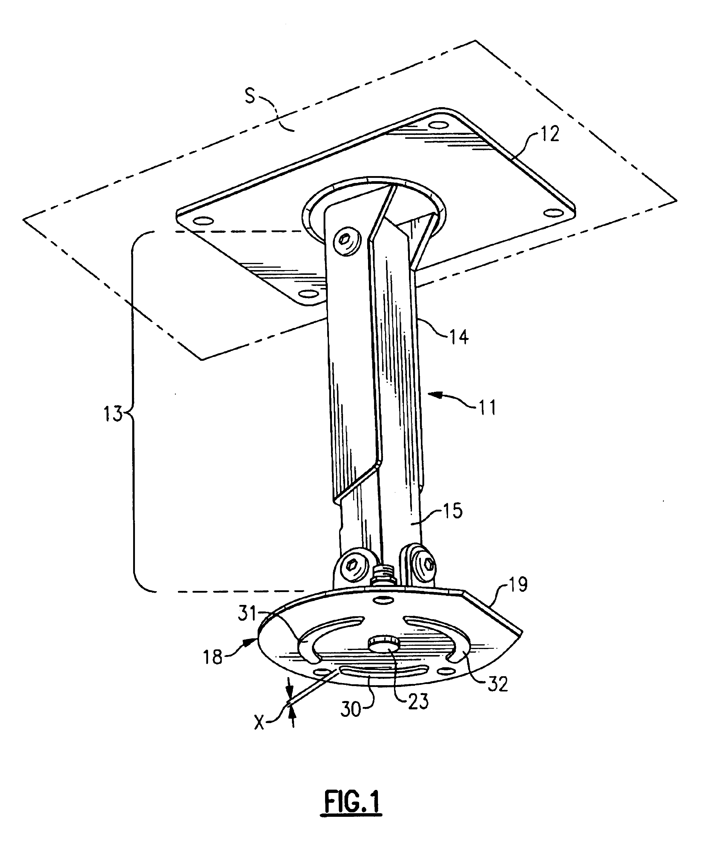
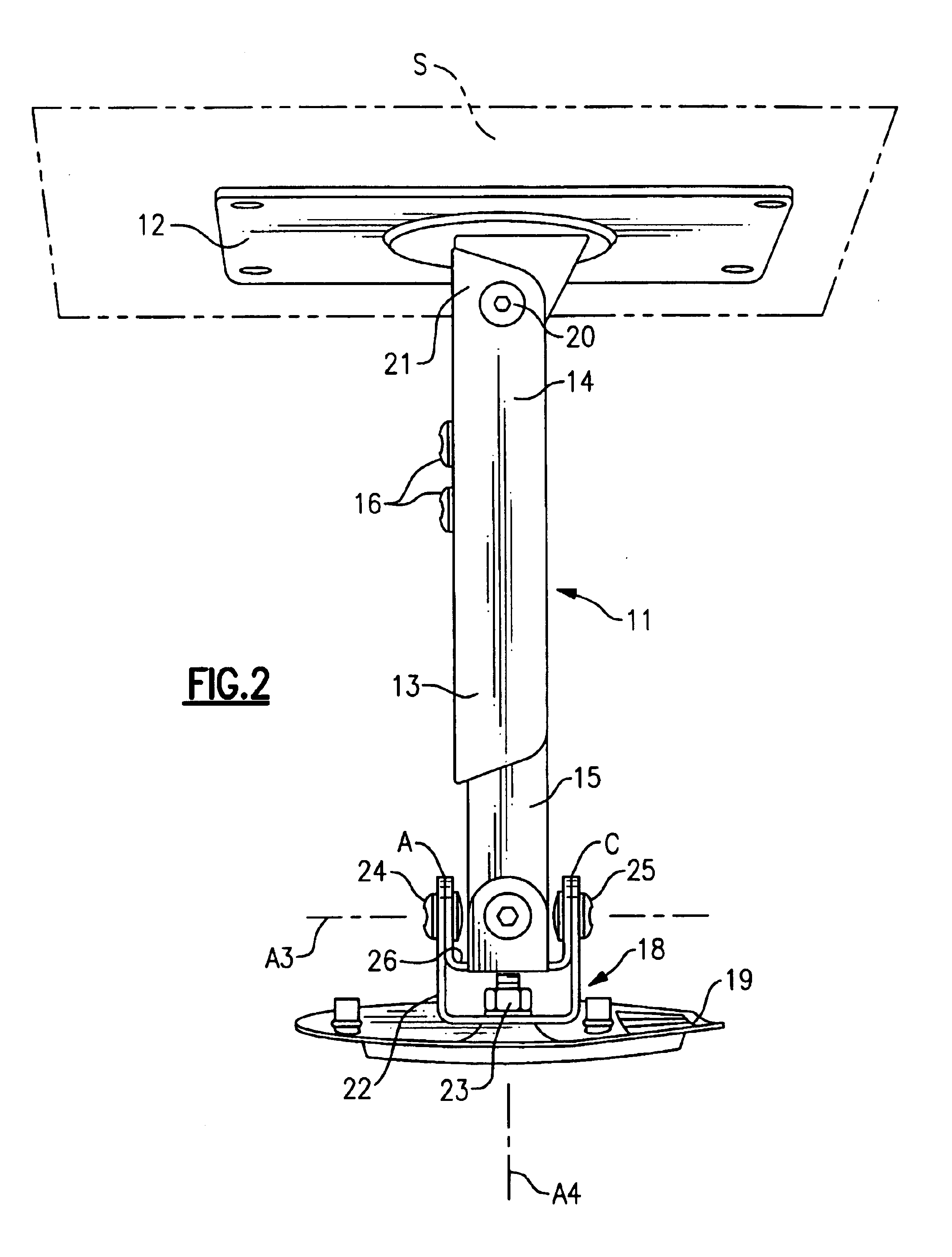
The figures show in whole or in part a mounting unit 11 for attaching a video projector (not shown) to a mounting surface which can be horizontal or vertical or at some angle intermediate the horizontal and the vertical comprising. The mounting unit 11 includes:

a rectangular anchorage plate 12 whereby the unit 11 can be attached to a mounting surface S (the surface S being shown as horizontal in FIGS. 1-4, vertical in FIG. 9 and at an angle in FIG. 10);

a beam 13 in two telescoping parts, upper part 14 and lower part 15, which are linked by clamp bolts 16 acting through slot 17 in upper part 14;

a carrier 18 comprising in combination a holding plate 19 and a mounting plate 20 (see FIGS. 7 and 8). The carrier 18 provides for the demountable attachment of a video projector to which mounting plate 20 has been previously fitted.

The mounting bracket 11 incorporates a number of pivots to enable a video projector mounted on a surface by means of the bracket 11 can be readily and accurately a...


PUM


Abstract

A mounting unit (11) for a attaching a working unit such as a video projector to a mounting surface which can be horizontal or vertical or at some angle intermediate the horizontal and the vertical comprising: an anchorage (12) whereby the unit can be attached to the mounting surface; a beam (13); a carrier (18) comprising in combination a holding plate (19) and a mounting plate; the carrier being adapted to provide for the attachment of a working unit to the mounting plate; a first pivot (20a) whereby a first end of the beam is pivotably attached to the anchorage to enable the beam to pivot about a first axis (a1); a second pivot whereby the other end of the beam to the first end is pivotably attached to the holding plate to enable the holding plate to pivot about a second axis (a2) parallel to the first axis; a third pivot (24) whereby the holding plate can pivot about a third axis perpendicular to the second axis; a fourth pivot (23) whereby the holding plate can pivot about a fourth axis (a4) perpendicular to the second and third axes; the carrier including mechanism whereby the mounting plate can be rotated about an fifth axis parallel to the holding plate.

Description

This invention relates to a mounting bracket. In particular it is concerned with a mounting bracket whereby a relatively heavy unit can be readily mounted to enable the unit to function in a required way with a pre-determined alignment. A typical such unit is a video projector though the invention is not limited to a mounting unit for such a projector.For the purposes of projecting a video recording or program there are advantages to having a video projector mounted well above the head height of a standing viewer. Typically in a hotel, conference centre or viewing room a mounting bracket at a relatively high locations provides for a projector attached to it to display on a screen without the projected image being interrupted by the passage of a late arrival. However the provision of a high mounting bracket can cause access and alignment problems when a projector is to be mounted by means of the bracket. In addition the bracket while allowing for the ready alignment of an attached pr...

Claims


Application Information

Patent Timeline
Patent Type & Authority Patents(United States)
IPC IPC(8): F16M11/12F16M11/02
CPCF16M11/10F16M11/12F16M11/2035F16M11/28F16M13/02Y10T403/32181F16M2200/027Y10S248/92Y10T403/32918Y10T403/32049
Inventor LIGERTWOOD, PETER
Owner LIGERTWOOD PETER
Learn More