Siding clip for supporting a panel

a technology for supporting clips and panels, applied in the direction of nails, mechanical equipment, walls, etc., can solve the problems of not providing convenience and economic benefits of supporting clips of current ar

Inactive Publication Date: 2004-04-27
BARBER ALAN E
View PDF17 Cites 20 Cited by
  • Summary
  • Abstract
  • Description
  • Claims
  • Application Information

AI Technical Summary

Problems solved by technology

However, supports of the current art do not provide the convenience and economy of enabling a single journeyman to secure a course of wallboards on vertical frame members.

Method used


Image

  • Siding clip for supporting a panel
  • Siding clip for supporting a panel
  • Siding clip for supporting a panel

Examples


Embodiment Construction

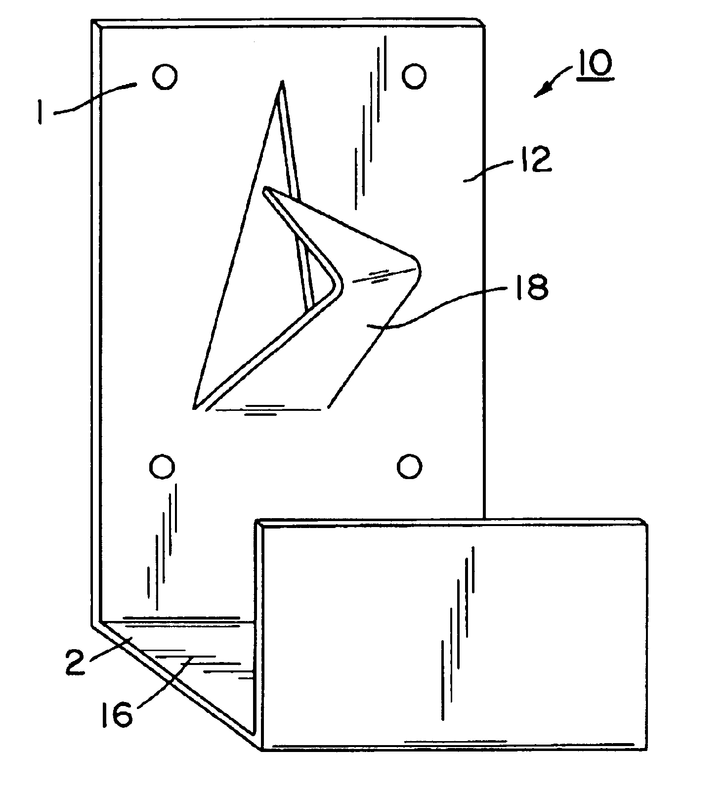
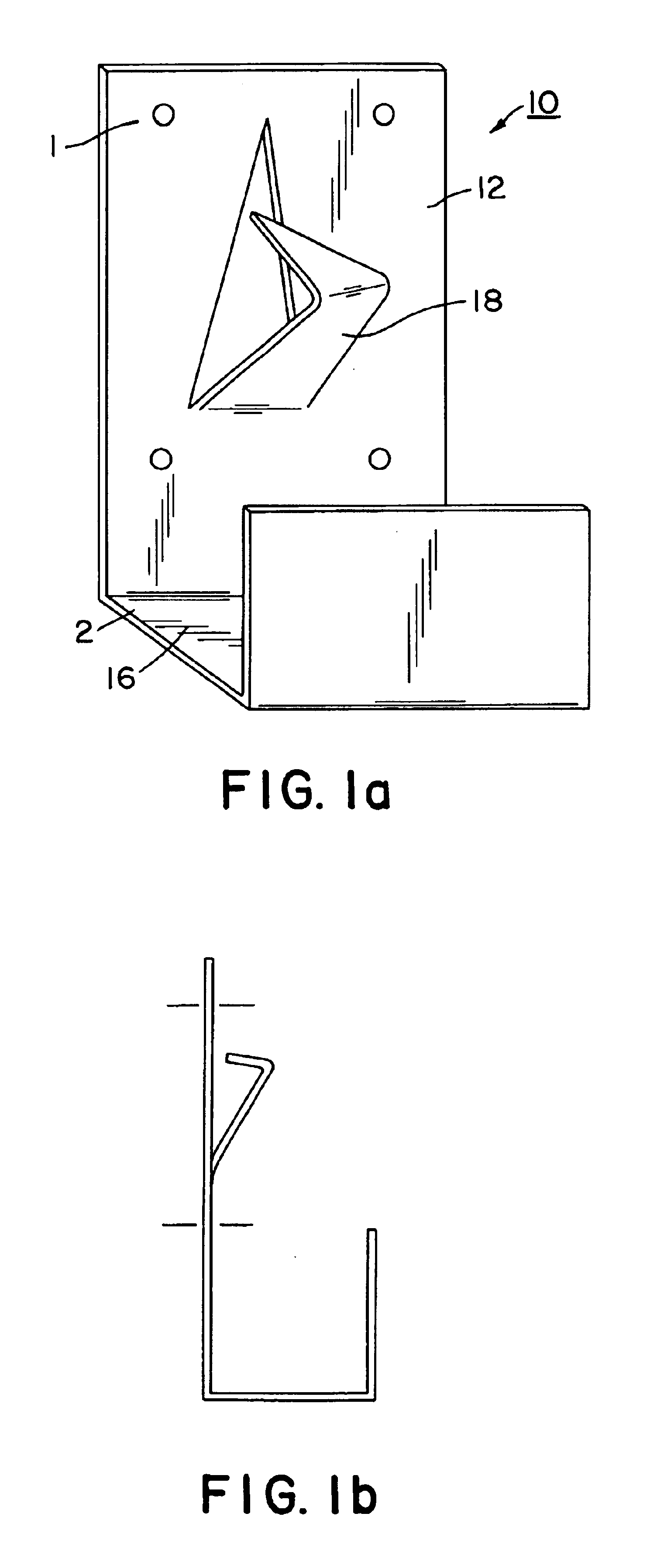
Turning now to a discussion of the drawings, FIG. 1 shows the bracket 10 of this invention including a long panel 12 and a short panel 14 joined to opposite edges of a joining panel 16. A punched out nailer 18 is shown extending perpendicularly from long panel 12.

The nailer is formed near a center of said long panel, and is a triangular area with one triangle edge joined to the long panel and bent angularly toward the short panel. A corner of the triangle opposite the triangle edge is bent toward the long panel .

An array of holes 20 (four are shown) through wide side 12. A line of perforations 22 is shown in the joining panel close to the long panel. The perforations permit the joining panel to be readily separated from the long panel 12 after the long panel 12 is nailed to a vertical stud and the wall board has been placed on the bracket and nailed to the stud. Therefore, the remaining panel is hidden from view after the wallboard is mounted.

FIG. 1b is a side view of FIG. 1a.
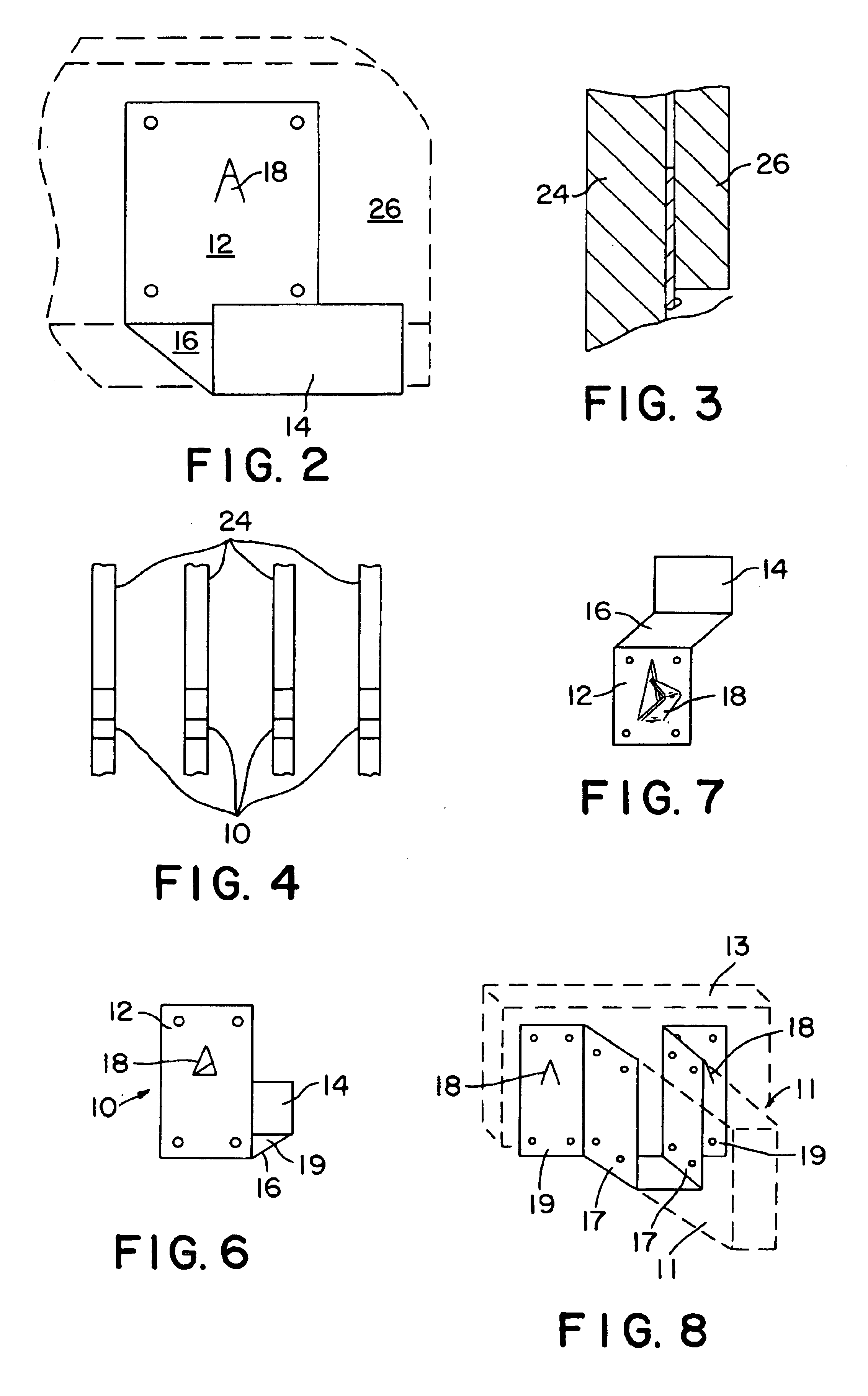
FIG. 2...


PUM


Abstract

A bracket for aiding in the mounting of a course of wallboards onto a frame of vertical studs including a channel having a short leg joined to a long panel and a punched out nailer extending from the long panel. First, the pointed free end of the nailer is driven into a stud permitting the user to check alignment of a row of the brackets before permanently securing each bracket to its respective stud by driving nails through apertures in the bracket into the stud. The board is then supported in the bracket against the stud and nailed to the stud. The bracket has a line of perforations that permits snapping the exposed part of the bracket from the stud.

Description

This invention is related to jigs and hardware used in the construction of frame buildings and particularly to a support secured to a building frame for holding a board (e.g., wallboard) in place while the board is secured to the frame. In the context of this specification, the term, "board" is understood to mean any large panel such as a sheet of plywood, fiberboard, sheetrock, plastic used to build walls by the construction industry.BACKGROUND AND INFORMATION DISCLOSUREBuilding the typical frame construction includes the operation of securing boards (wallboards) to the wooden frame. This is typically a two man operation requiring location for placement of the wallboard, and holding the wallboard in place while fasteners are applied to securing the wallboard to the vertical frame member.A number of jigs have been disclosed for joining members, including frame members to wallboard and board members.For example, U.S. Pat. No. 5,642,595 to Gold et al discloses a channel-like bracket f...

Claims


Application Information

Patent Timeline
Patent Type & Authority Patents(United States)
IPC IPC(8): E04F13/08E04B2/74F16B15/00
CPCE04B2/7457E04F13/0841F16B15/0046
Inventor BARBER, ALAN E.
Owner BARBER ALAN E
Why Eureka
Try Eureka