Retractable anchor device and method of mounting the anchor device

a technology of a retractable anchor and a fixing device, which is applied in the directions of transportation and packaging, load securing, transportation items, etc., can solve the problems of not having the ability to completely out of the way the anchor or the fixing device, and none of these anchors or tie-down devices allow the fixing device to completely out of the way

Inactive Publication Date: 2004-07-20
PRETA JOHN
View PDF43 Cites 57 Cited by
  • Summary
  • Abstract
  • Description
  • Claims
  • Application Information

AI Technical Summary

Problems solved by technology

However, none of these documents disclose a U-shaped member which can slidably retract and / or which is either biased towards a retracted position or is movable towards a retracted position via an actuator.
Such anchors, however, do not have the ability to retract completely out of the way when they experience a predetermined external force.
None of these anchor or tie-down devices allow the fixing device to retract completely out of the way or to disappear into a body.
Accordingly, none of these devices retract a U-shaped member out of the way so that it will not catch an occupant's clothing.
Moreover, such devices do not have a locking system which locks the a U-shaped member in an extended position while being biased towards a retracted position.
Finally, none of these device disclose the use of an actuator to control the position of the U-shaped member, much less, an actuator which uses a load-sensing and / or force-sensing system / circuit / device to ensure that the U-shaped member is moved to an extended position and / or moved to a retracted position when subjected to a predetermined external force.
Finally, none of the prior art devices disclose of suggest a U-shaped member which is both rotatably mounted and biased towards the retracted position, or one which discloses any of the embodiments described herein, or which have their inherent advantages.

Method used


Image

  • Retractable anchor device and method of mounting the anchor device
  • Retractable anchor device and method of mounting the anchor device
  • Retractable anchor device and method of mounting the anchor device

Examples


Embodiment Construction

The particulars shown herein are by way of example and for purposes of illustrative discussion of the embodiments of the present invention only and are presented in the cause of providing what is believed to be the most useful and readily understood description of the principles and conceptual aspects of the present invention. In this regard, no attempt is made to show structural details of the present invention in more detail than is necessary for the fundamental understanding of the present invention, the description taken with the drawings making apparent to those skilled in the art how the several forms of the present invention may be embodied in practice. Moreover, the various embodiments are shown having relative scale (i.e.; enabling one to compare relative sizes of the various features) for the purpose of illustrating various preferred embodiments. However, the invention contemplates numerous variations in sizes as well as relative sizes of the various features.
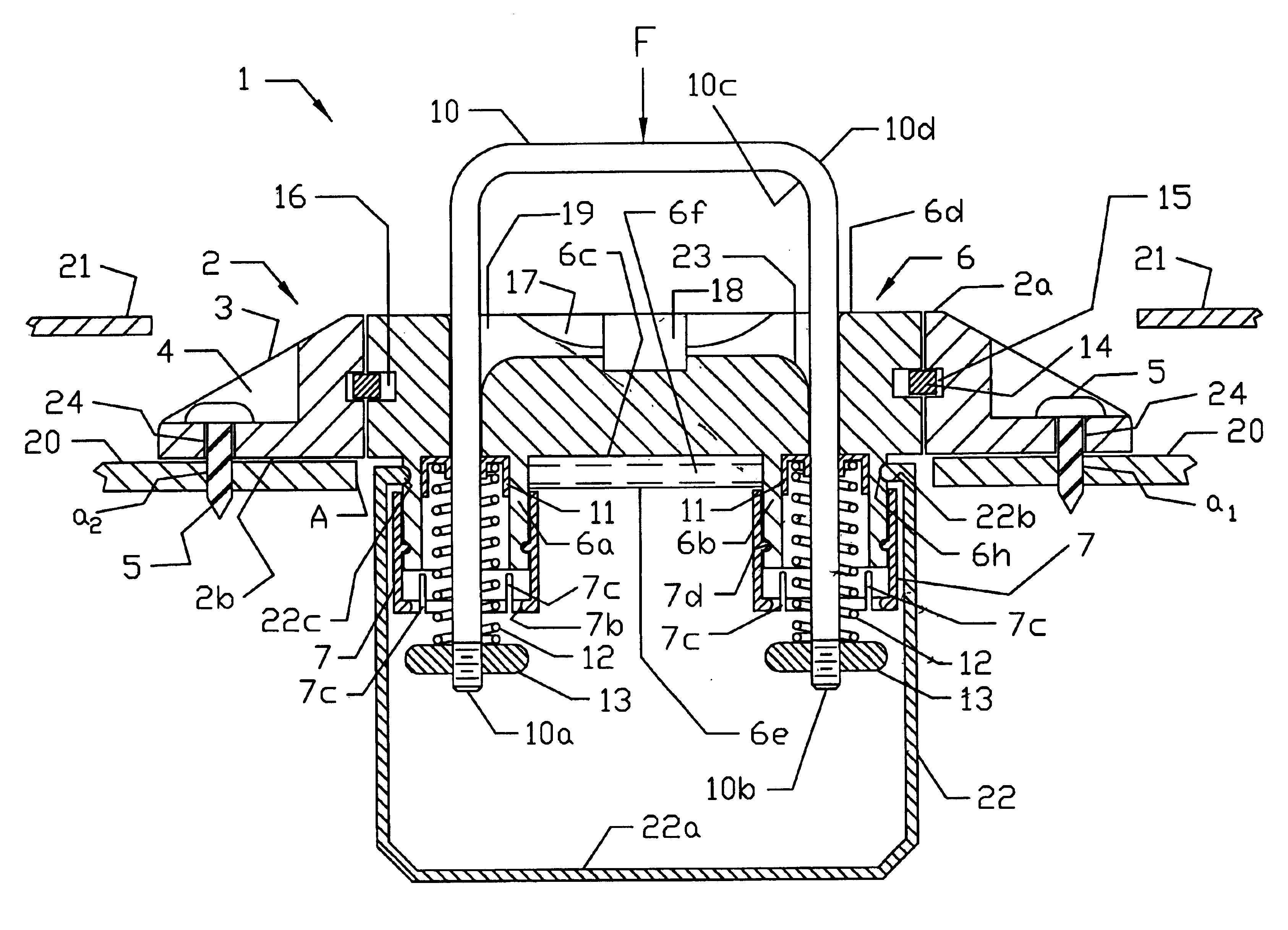
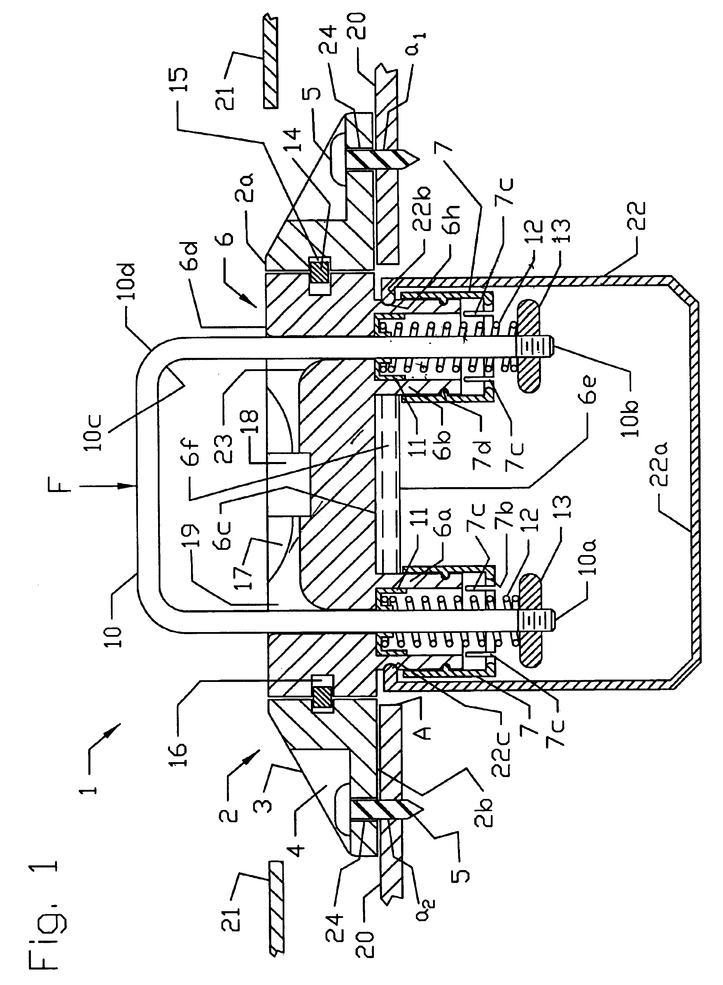
FIG. 1 shows ...


PUM


Abstract

Retractable anchor device includes a mounting part which is securable to a surface and a generally U-shaped member to which a tension member can be secured. The U-shaped member is slidably mounted to the mounting part and including a first end and a second end. A retracting system is included that causes the U-shaped member to move to a retracted position when the U-shaped member experiences a predetermined external force sufficient to disengage the locking system. The retracting system has at least one of (a) first and second biasing mechanisms wherein the first biasing mechanism biases the first end towards the retracted position and the second biasing mechanism biases the second end towards the retracted position, or (b) an actuator, wherein the actuator moves the U-shaped member towards at least one of the extended position and the retracted position. The U-shaped member is movable between the extended position whereby at least a portion of the U-shaped member is positioned above an upper surface of the mounting part, and the retracted position whereby the U-shaped member is positioned approximately flush with or below the upper surface of the mounting part.

Description

1. Field of the InventionThe invention relates to a retractable anchor device which can be used to tie-down articles. The anchor is particularly useful when mounted to vehicles or boats. The anchor may also be used on military vehicles such as trucks, transport aircraft and ships, as well as, on vehicles which are designed to operate in the near zero gravity of space.In one embodiment, the anchor device is attached to a surface and has a retractable U-shaped member to which a rope, strap, wire or other tension member (flexible or otherwise) can be secured. The U-shaped member is biased towards a retracted position and the anchor uses a locking system which holds the U-shaped member in the extended position. If the U-shaped member experiences a sufficient external force, (i.e., a sufficient to disengage the locking system) the U-shaped member is automatically caused to retract towards the retracted position. In another embodiment of the anchor, an actuator / sensing system is utilized ...

Claims


Application Information

Patent Timeline
Patent Type & Authority Patents(United States)
IPC IPC(8): B60P7/08B60P7/06
CPCB60P7/0807
Inventor PRETA, JOHN
Owner PRETA JOHN
Why Eureka
Try Eureka