Segmented ring guide for rolling mill laying head

a technology of laying head and ring guide, which is applied in the direction of guiding/positioning/aligning arrangements, work manipulation, etc., can solve the problems of accelerating wear, requiring replacement of the entire trough, and causing difficulties in unitary construction of the trough

a technology of laying head and ring guide, which is applied in the direction of guiding/positioning/aligning arrangements, work manipulation, etc., can solve the problems of accelerating wear, requiring replacement of the entire trough, and causing difficulties in unitary construction of the trough

US6769641B2Inactive Publication Date: 2004-08-03PRIMETALS TECH USA

Image

  • Segmented ring guide for rolling mill laying head
  • Segmented ring guide for rolling mill laying head
  • Segmented ring guide for rolling mill laying head

Examples


Embodiment Construction

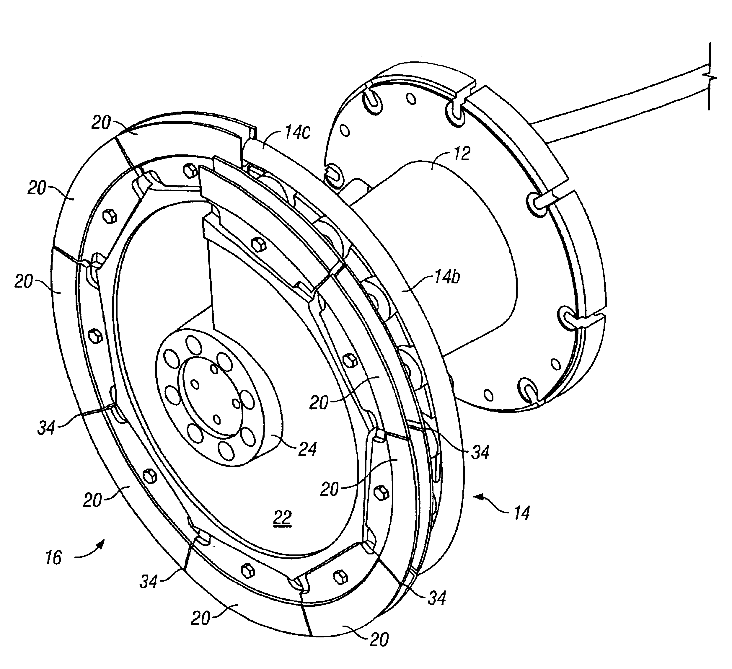
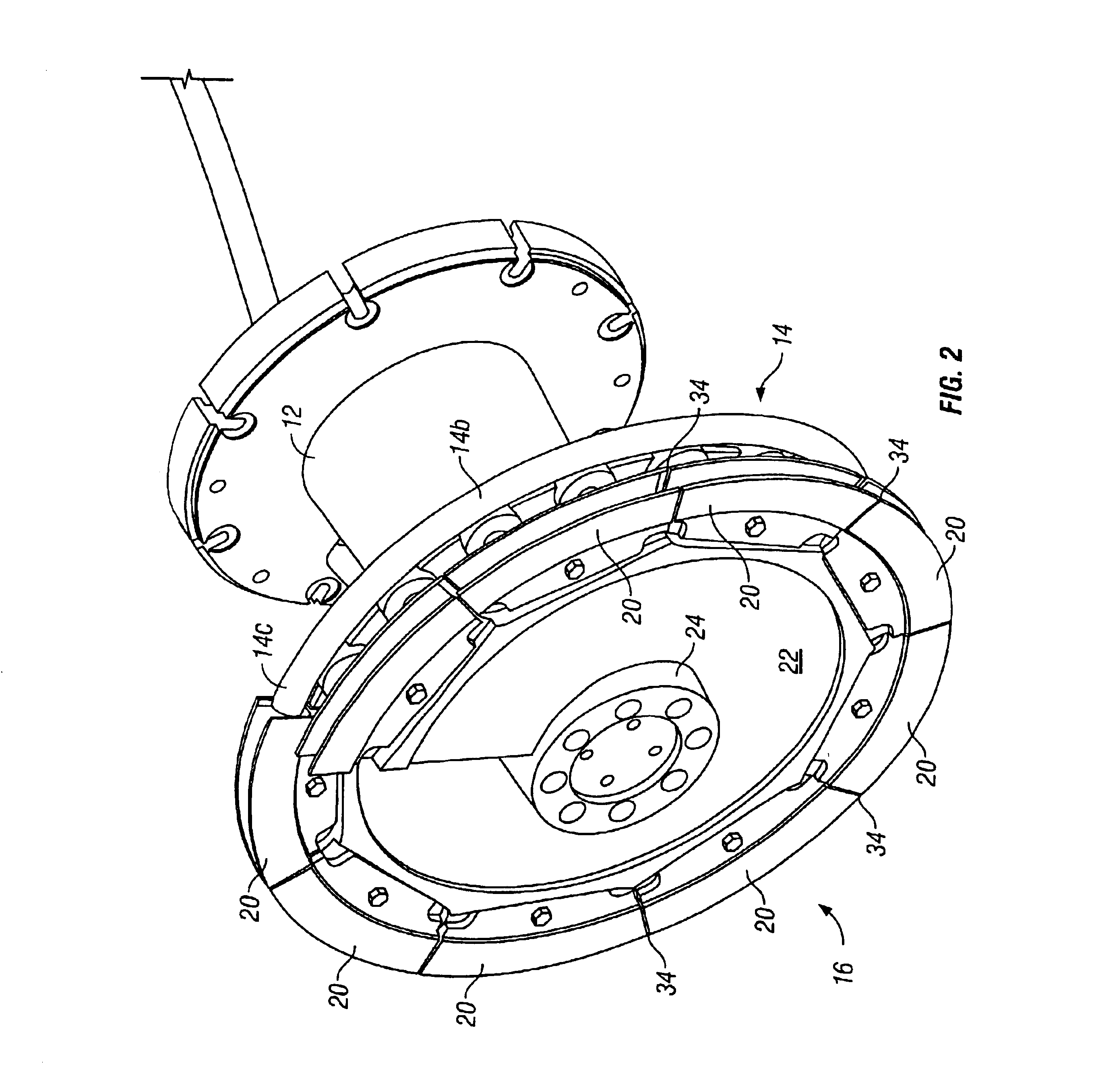
It will be seen by additional reference to FIG. 2 that a helical trough 16' in accordance with the present invention is made up of channel-shaped guide segments 20 supported end-to-end on a helical support plate 22 having a hub 24 removably secured to the end of the quill 12.

FIG. 3 shows the assembly of the helical support plate 22 and guide segments 20 removed from the quill, FIG. 4 is an exploded view of the components of the assembly, FIG. 5 shows the helical support plate 22 by itself, and FIG. 6 shows an end view of a typical guide segment. The individual guide segments 20 have generally U-shaped guide channels with mounting flanges 26. The mounting flanges 26 are angularly offset with respect to their respective guide channels, and are advantageously provided with laterally projecting shoulders 28 configured and dimensioned to be seated in locating grooves 30 in flat recessed mounting surfaces 31 located around the flank of the helical support plate 22. The guide segments are ...


PUM

PropertyMeasurementUnit
resistanceaaaaaaaaaa
sizeaaaaaaaaaa
strengthaaaaaaaaaa

Abstract

A laying has a quill rotatable about an axis, and a pipe carried on the quill. The pipe has an entry end arranged to receive a product, and an intermediate portion defining a curved guide path leading from the entry and to a delivery end spaced radially from the quill axis and from which the product is discharged as a helical series of rings. A guide defines a helical extension of the guide path, and comprises a helical support plate projecting outwardly from the quill. A plurality of channel-shaped guide sections supported end to end on the support plate. The guide sections form a segmented radially outwardly facing helical trough surrounded by a cylindrical shroud that cooperates with the guide sections to definee radially and axially confined helical extension of the guide path.

Description

BACKGROUND OF DISCUSSION1. Field of the InventionThis invention relates to high speed rod rolling mills, and is concerned in particular with an improvement to the laying heads employed in such mills to form the hot rolled product into a series of rings.2. Description of the Prior ArtWith reference to FIG. 1, a typical laying head includes a housing 10 containing a rotatably driven hollow quill 12. A three dimensionally curved laying pipe 14 is carried by the quill 12. The laying pipe has an entry end 14a aligned with the rotational axis X of the quill, and a curved intermediate section 14b leading to a delivery end 14c spaced radially from axis X.Hot rolled steel rod is delivered to the entry end 14a of the delivery pipe along axis X, and exits from the delivery end 14c as a helical formation of rings.Upon exiting from the delivery end 14c of the laying pipe, the rings are additionally confined and moved forward by a helical trough 16 surrounded by a cylindrical shroud 18.The guide ...

Claims


Application Information

Patent Timeline
03 Aug 2004
Publication
US6769641B2
IPC
B21C47/02; B21C47/14; B21B39/20; B21B39/14
CPC
B21C47/143; B21C47/14; B21C47/10
Inventors
PARISEAU, DAVID L.; PLANTE, KENNETH