Electric connector provided with a shield plate equipped with thrust shoulders

a shield plate and shield plate technology, applied in the field of hardmetric, can solve the problems of time-consuming and labor-intensive process

Inactive Publication Date: 2004-09-14
HONDA TSUSHIN IND
View PDF5 Cites 71 Cited by
  • Summary
  • Abstract
  • Description
  • Claims
  • Application Information

AI Technical Summary

Problems solved by technology

Also disadvantageously, before applying a thrust to the connector the "L"-shaped shield plate needs to be tentatively fastened to the connector body 12 with a piece of double-sided adhesive tape.
This is an elaborate, time consuming process.

Method used


Image

  • Electric connector provided with a shield plate equipped with thrust shoulders
  • Electric connector provided with a shield plate equipped with thrust shoulders
  • Electric connector provided with a shield plate equipped with thrust shoulders

Examples


Embodiment Construction

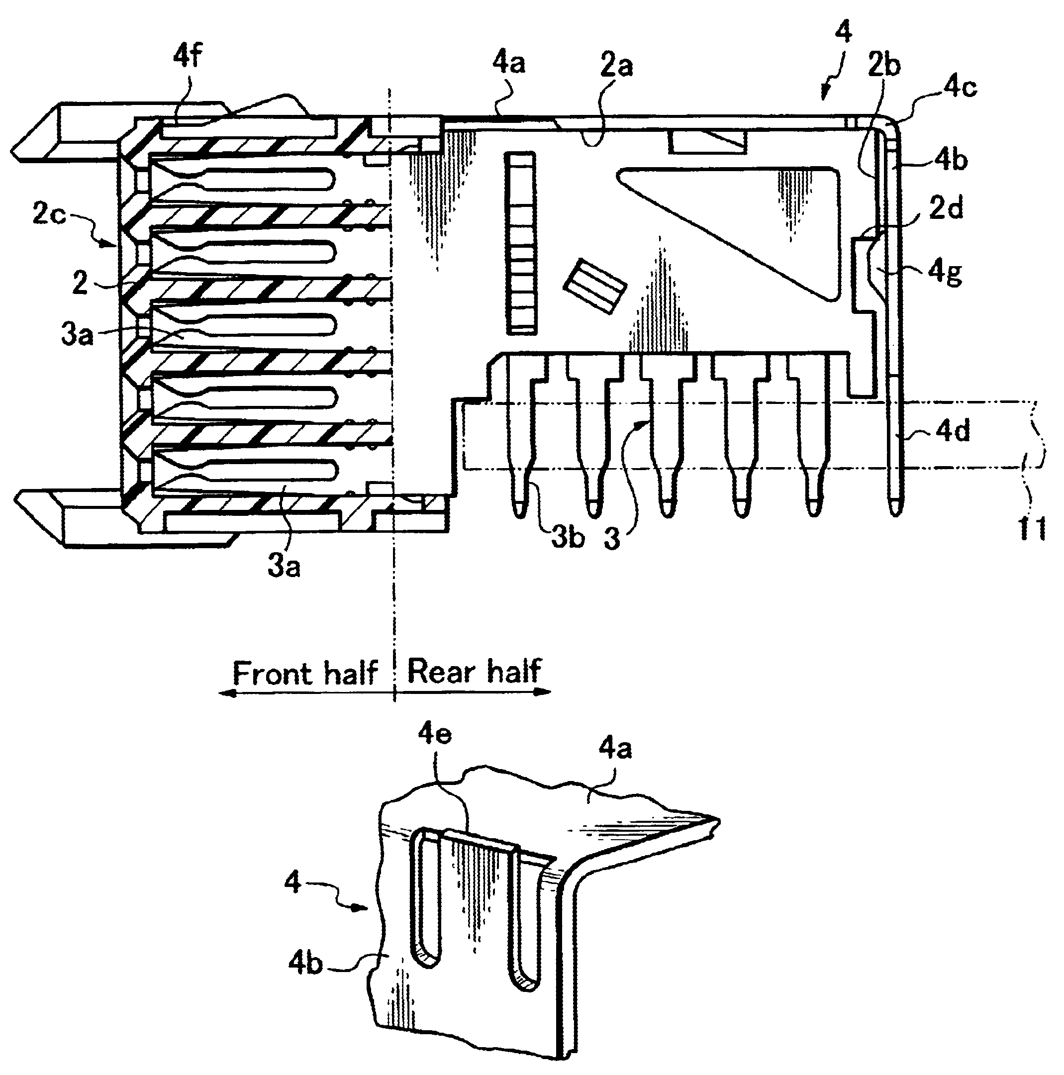
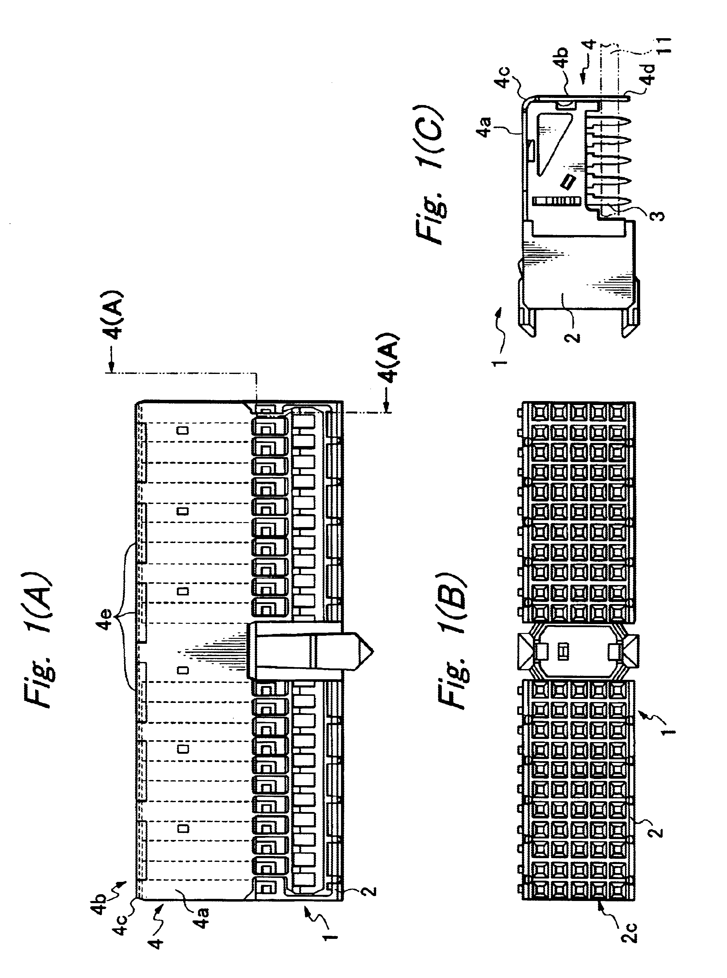
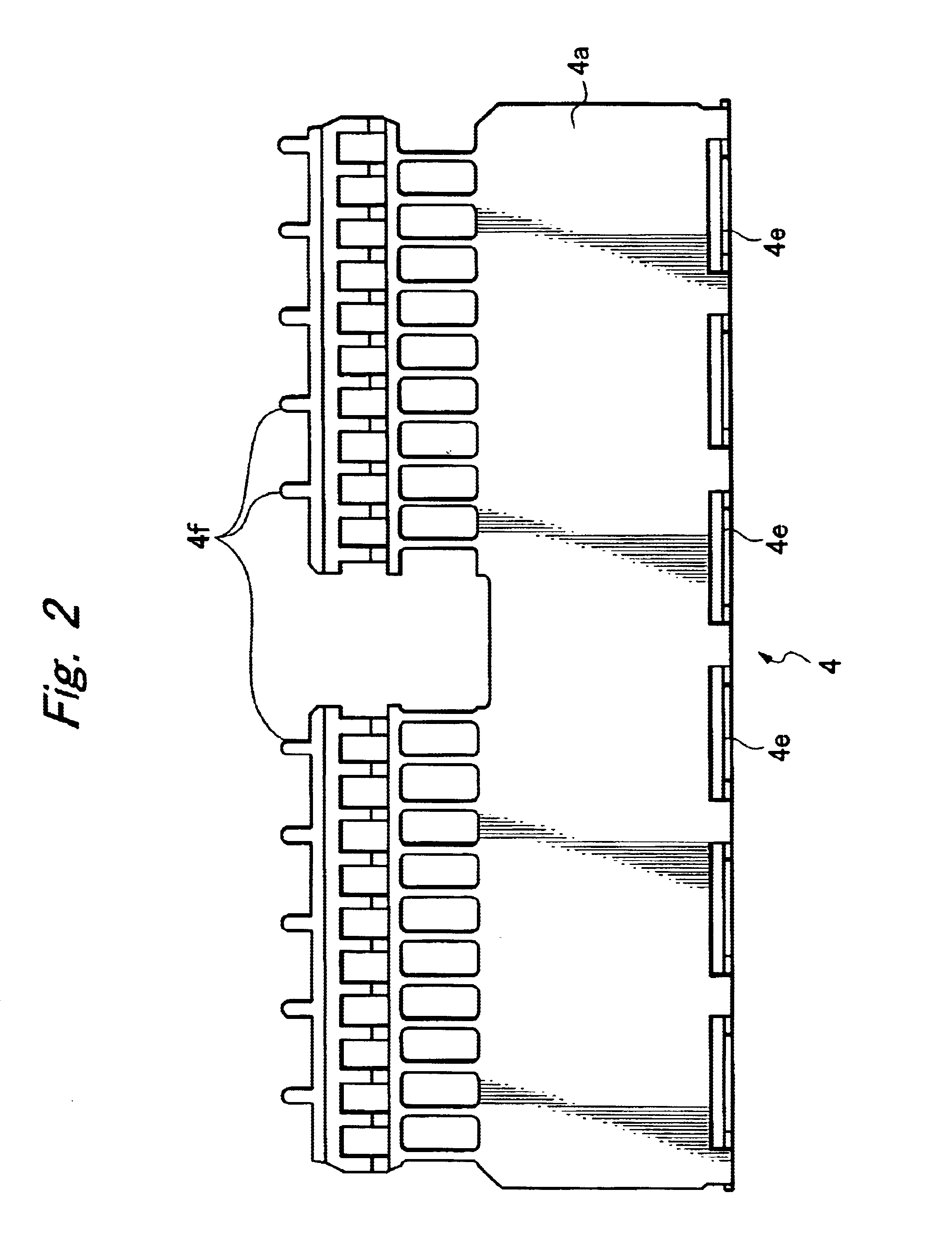
Referring to FIGS. 1(A)-(C), an HM connector 1 comprises a connector body 2 having contact pieces 3 insert-molded therein and an "L"-shaped shield plate 4 applied to the connector body 2 with its horizontal and vertical sections 4a and 4b lying on the top surface 2a and rear side 2b of the connector body 2. The shield plate 4 has press-fit portions 4d integrally connected to the lower end of the vertical section 4b of the shield plate 4.

Referring to FIG. 4(A), the connector body 2 comprises front and rear halves integrally connected by insert molding contact pieces 3. The front half has a plurality of female receptacles 2c made in a lattice form, and the female contact portions 3a are inserted in the female receptacles 2c. The rear half of the contact body 2 has the intermediate lengths of the contact pieces 3 embedded therein. The vertical extensions of the contact pieces 3 partly appear from the bottom of the rear half of the conductor body 2 to provide male contact portions 3b. A...


PUM


Abstract

A shielded electrical connector includes a connector body having contact pieces embedded therein and an "L"-shaped shield plate applied to the connector body with its horizontal and vertical sections lying on the top surface and rear side of the connector body, the shield plate having press-fit portions integrally connected to the lower end of the vertical section. The shield plate has thrust shoulders formed at its horizontal-to-vertical transition for use in pushing the press-fit portions. The electrical connector can be fixed to a printed circuit board by applying a push to the thrust shoulders of the shield plate, thereby pushing the press-fit portions of the shield plate right in the through holes in exact linear-alignment with the through holes. Thus, a strong thrust can be transmitted to each press-fit portion without causing it to be deformed or bent.

Description

1. Field of the InventionThe present invention relates to a hard-metric (abbreviated as HM) connector of the type used in exchangers, servers or computers. It uses a press-fit type of shield plate to facilitate the mounting of the shielded connector onto a printed circuit board.2. Related ArtReferring to FIGS. 5(A), (B) and (C) and FIG. 6, a conventional electrical connector 10 has a press-fit type of "L"-shaped shield plate 13 tentatively fastened to its body 12 by making the engagement extensions of a flat top 13a of the shield 13 to be engaged on a front side of the connector body 12. The shield plate 13 has a vertical section 13b extending downward via bent round portion 13c. The rear part of the connector body 12 has its bottom raised to a level higher than the bottom of the front part, thus leaving a space to accommodate a printed circuit board 11. As seen from FIGS. 5(C) and 6, the rear part of the connector body has the male contact portions 3b of the contact pieces 3 projec...

Claims


Application Information

Patent Timeline
Patent Type & Authority Patents(United States)
IPC IPC(8): H01R12/00H01R12/16H01R13/648H01R24/00
CPCH01R12/724H01R23/6873H01R12/58H01R13/658
Inventor ONO, KOJIOOAKU, KIYOSHI
Owner HONDA TSUSHIN IND
Why Eureka
Try Eureka