

Wave gear device torque detection method
- Summary
- Abstract
- Description
- Claims
- Application Information
AI Technical Summary
Benefits of technology
Problems solved by technology
Method used
Image

Examples
Embodiment Construction
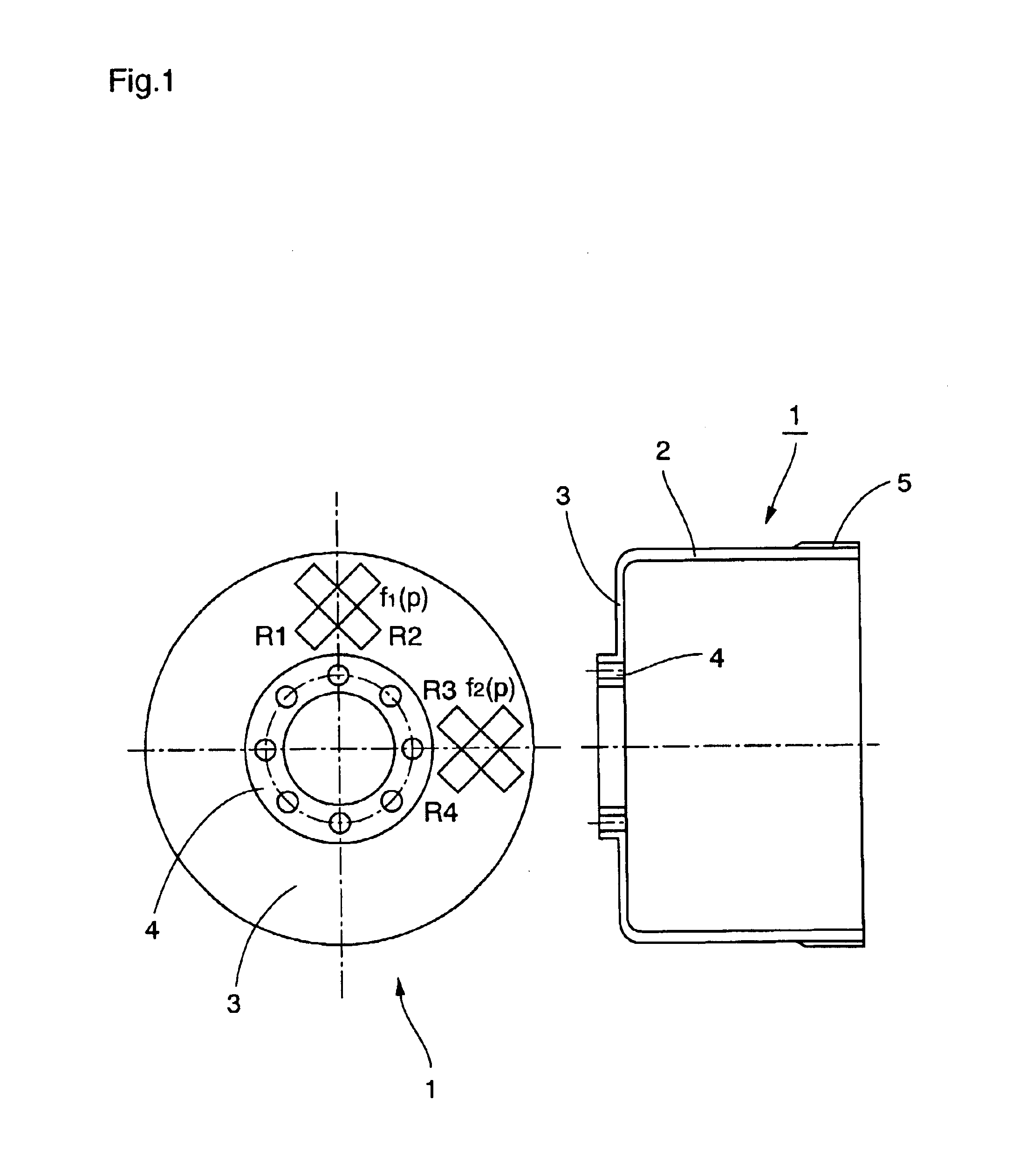
The wave gear device torque detection method according to the present invention will now be described with reference to the drawings.
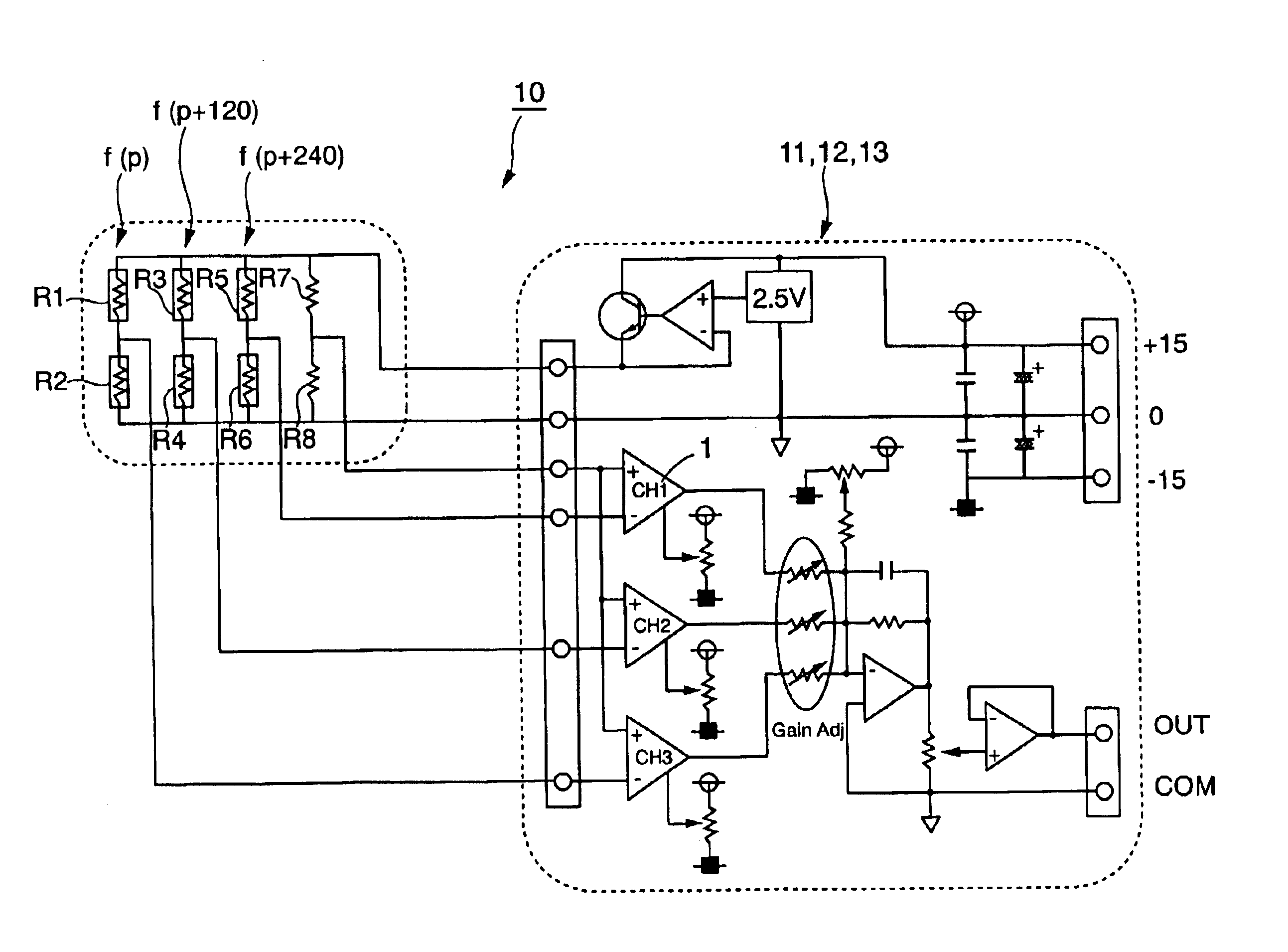
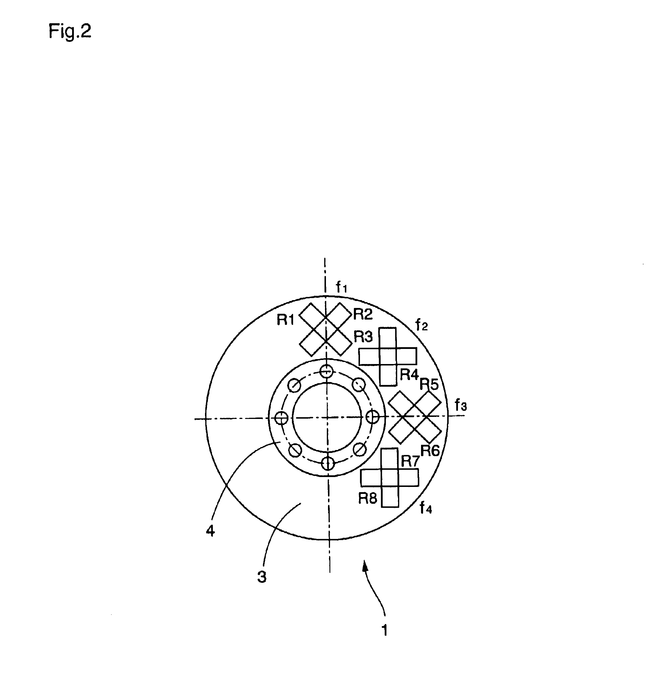
Equation (1) expresses the rotational ripple component included in the output of strain gauge groups f1 to f4 affixed to the surface of the diaphragm 3 of the cup-shaped flexible external gear 1 at a prescribed angular spacing, as shown in FIG. 2. Note that equations (1) to (4) represent an example in which rotational ripple includes only secondary and quaternary components. f1(p)=a11sin(2p+ψ11)+a21sin(4p+ψ21)f2(p)=a12sin(2p+ψ12)-a22sin(4p+ψ22)f3(p)=-a13sin(2p+ψ13)+a23sin(4p+ψ23)f4(p)=-a14sin(2p+ψ14)-a24sin(4p+ψ24)}(1)
where p: rotational angle of the wave generator,f1(p)-f4(p): ripple component output of each strain gauge,h(p): ripple component output included in composite output of the strain gauges,a11-a24: amplitude of each frequency component of each strain gauge, having error component,ψ11-ψ24: phase error of each frequ...
PUM
 Abstract
Description
Claims
Application Information