Bumper step

a technology of bumper step and step assembly, which is applied in the direction of vehicle components, steps arrangement, construction, etc., can solve the problems of not being useful for mounting, assembly is not designed to be mounted, and the 996 patent suffers from many problems

Inactive Publication Date: 2005-01-11
NISSAN MOTOR CO LTD
View PDF68 Cites 94 Cited by
  • Summary
  • Abstract
  • Description
  • Claims
  • Application Information

AI Technical Summary

Problems solved by technology

The '996 patent suffers from many problems characteristic of existing step assemblies.
In one aspect, the '996 step assembly must be mounted on a vehicle tailgate, which typically is not designed to support substantial loading.
Thus, the '996 step assembly is not designed to be mounted facing a side of the vehicle (for example, a passenger side to facilitate bed access from the passenger side).
Further, the '996 step assembly is designed to be mounted on a vehicle with a tailgate, thus it is not useful for mounting on a cargo van or delivery truck which may not have a tailgate surface for mounting the step assembly.
In a related aspect, mounting the '996 step assembly on the tailgate may not be aesthetically pleasing, as the step assembly is visible even in a stored position.
In another aspect, the '996 step assembly freely rotates about a hinge pivot rod, and does not provide a lockable stepping platform for the user, because the freely rotating hinge does not provide a secure locking member.
The '842 patent, however, also suffers from many problems characteristic of existing step assemblies.
Further, the '842 step assembly may also not be aesthetically pleasing as it is also visible in the stored position.

Method used


Image

  • Bumper step
  • Bumper step
  • Bumper step

Examples


first embodiment

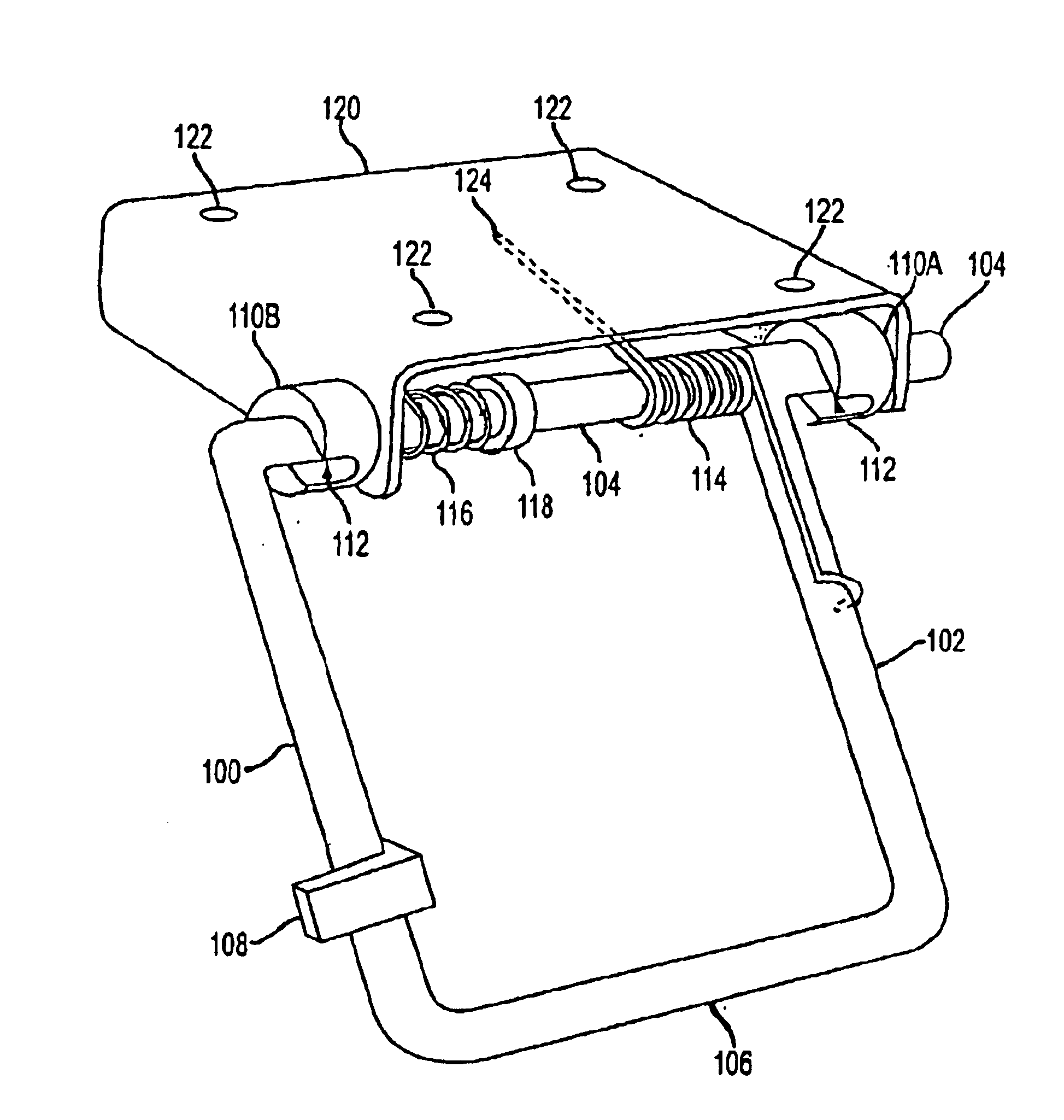
In a first embodiment as shown in FIG. 1, a step assembly is shown in a schematic view (preferably for a passenger side of a vehicle). A step frame is shown comprising a first leg 100 and a second leg 102 oriented parallel to, and horizontally spaced from, one another. An axle 104 is shown connected at an upper end of legs 100 and 102. Step member 106 is shown connected between legs 100 and 102 at a lower end of legs 100 and 102. Optional operating tab 108 is shown connected to leg 100 for moving the step frame between a stored position and a deployed position. Optional operating tab 108 may also be connected to leg 102, or step member 106.

Alternatively, the step frame may comprise one or more legs in a substantially “L” shape, a “U” shape, a “∇” shape, a “Δ” shape, a trapezoidal shape, a ramp frame, or other configurations as would be readily apparent to one skilled in the art after reading this disclosure. Hence, a telescoping or multiple sectioned ramp such as a loading ramp, is ...

second embodiment

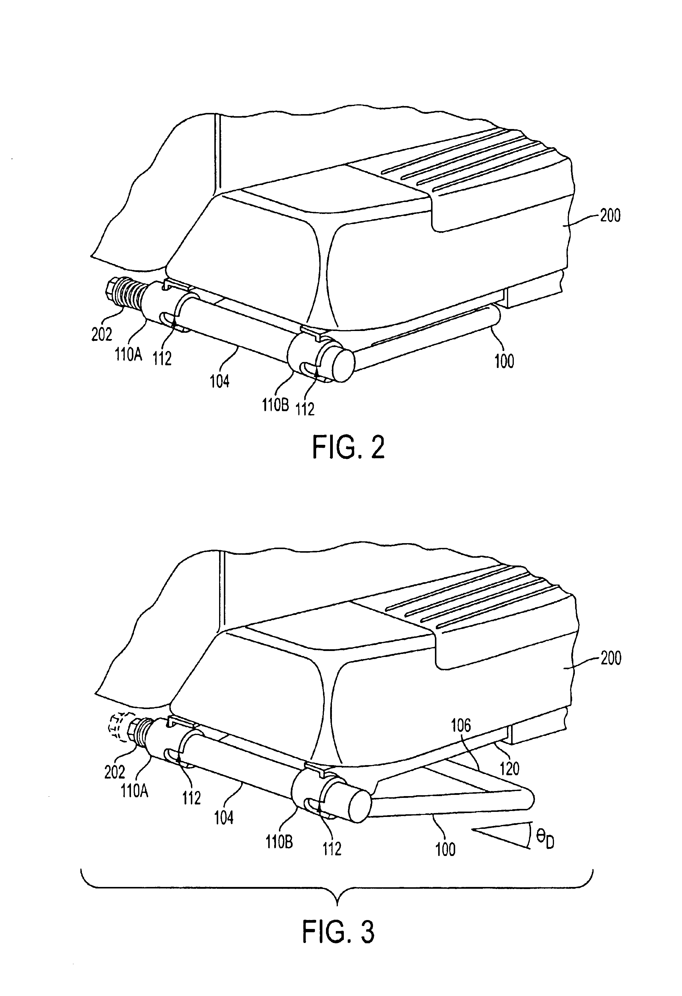
In a second embodiment as shown in FIGS. 2-5, a step assembly according to the present invention is shown mounted to a vehicle bumper 200 (preferably for a driver side of a vehicle). Alternatively, the step assembly may be mounted directly on a frame member of a vehicle. Mounting the step assembly on a vehicle bumper or frame member facilitates deployment of the step assembly independent of a tailgate position. Further, the step assembly is typically mounted on a vehicle bumper or frame member because they are generally designed to withstand heavier loads than a tailgate. FIG. 2 shows the step assembly in a stored position. FIG. 3 shows the step assembly moving between a stored position and a deployed position. FIG. 4 shows the step assembly in a deployed position. FIG. 5 shows a stored position 500 and a deployed position 502.

In the second embodiment as shown in FIG. 4, the step assembly may comprise a spring 202 to retain the step frame in the notches 112 of boss 110A and boss 110...

third embodiment

In a third embodiment as shown in FIGS. 6 and 7, step assembly 600 may be mounted on a vehicle bumper 200 on the side of a vehicle 602 to facilitate access to the bed from the side (either driver and / or passenger side).


PUM


Abstract

A step assembly is provided having a step frame mounted for movement relative to a mounting surface between a deployed position and a stored position (or between a stored position and a deployed position), and at least one boss, the boss having a notch for holding the step frame in the deployed position. The step frame preferably has at least two legs oriented parallel to each other, and horizontally spaced from one another, each of the legs defining an upper end and a lower end, an axle connected at the upper end of the at least two legs, and a step member connected between the at least two legs proximate to the lower ends thereof.

Description

BACKGROUND OF THE INVENTIONA. Field of the InventionThe invention relates generally to a step assembly, and more particularly to a vehicle step assembly, such as for a pickup truck, a sport utility vehicle (SUV), a non-commercial vehicle, an all terrain vehicle (ATV) or other land vehicle for example.B. Background of the InventionPresently, one step assembly is described in U.S. Pat. No. 5,732,996 (the “'996 patent”). The '996 patent discloses a tailgate step with a hinge assembly and a step assembly attached to the inside panel of the tailgate near its upper edge. The step assembly in the '996 patent freely rotates about a hinge pivot rod, which is positioned proximate and parallel to the upper edge of the tailgate. The step frame rests in a deployed position by contact with the tailgate due to the positioning of the hinge pivot rod.The '996 patent suffers from many problems characteristic of existing step assemblies. In one aspect, the '996 step assembly must be mounted on a vehic...

Claims


Application Information

Patent Timeline
Patent Type & Authority Patents(United States)
IPC IPC(8): B60R3/00B60R3/02
CPCB60R3/02
Inventor ANDERSON, MICHAEL D.BALL, STEPHEN D.
Owner NISSAN MOTOR CO LTD
Why Eureka
Try Eureka