U-shaped wire rope clamp

Inactive Publication Date: 2005-01-18
WARREN ROBERT E
View PDF16 Cites 39 Cited by
  • Summary
  • Abstract
  • Description
  • Claims
  • Application Information

AI Technical Summary

Benefits of technology

In its simplest form, the present invention provides a wire rope clamp comprising a U-shaped clamp member having a central fold therein, said clamp member having a first plate portion on one end of said central fold and a second plate portion on an opposite end of said central fold, said clamp member having at least one opening located on said central fold between opposite sides of said clamp member for a

Problems solved by technology

Because the devices include four separate pieces, assembly may be difficult.
Further, because of the circular cross section of the U-bolt member, a single concentrated contact with unconstrained pressure may be exerted onto the wire rope and thereby distort and weaken the wire rope.
Further, when two sections of the wire rope are connected, they typically become twisted and do not remain in a single plane causing uneven pressure.
However, the details regarding wire rope engaging surfaces 18 and 42 are not disclosed and thus distortion and weakening of the wire rope is still a possibility.
Also, this

Method used


Image

  • U-shaped wire rope clamp
  • U-shaped wire rope clamp
  • U-shaped wire rope clamp

Examples


Embodiment Construction

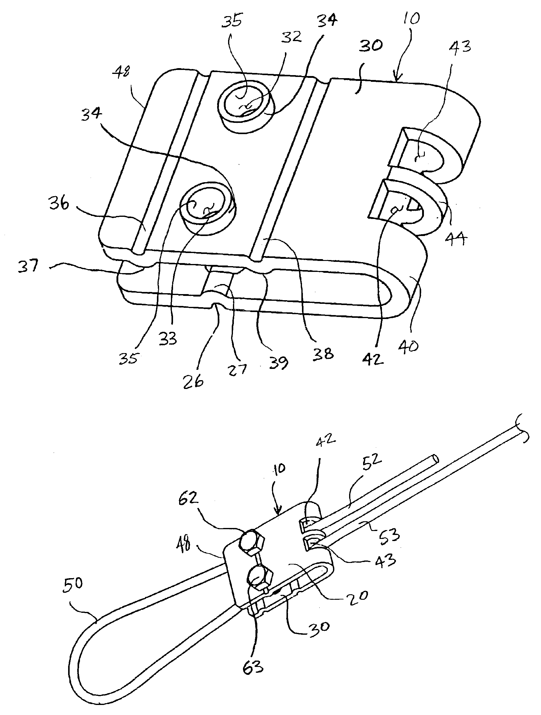
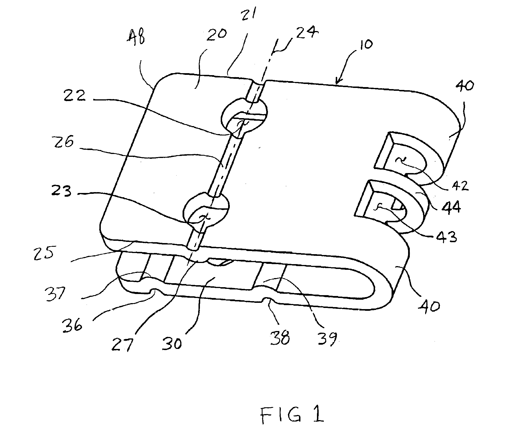
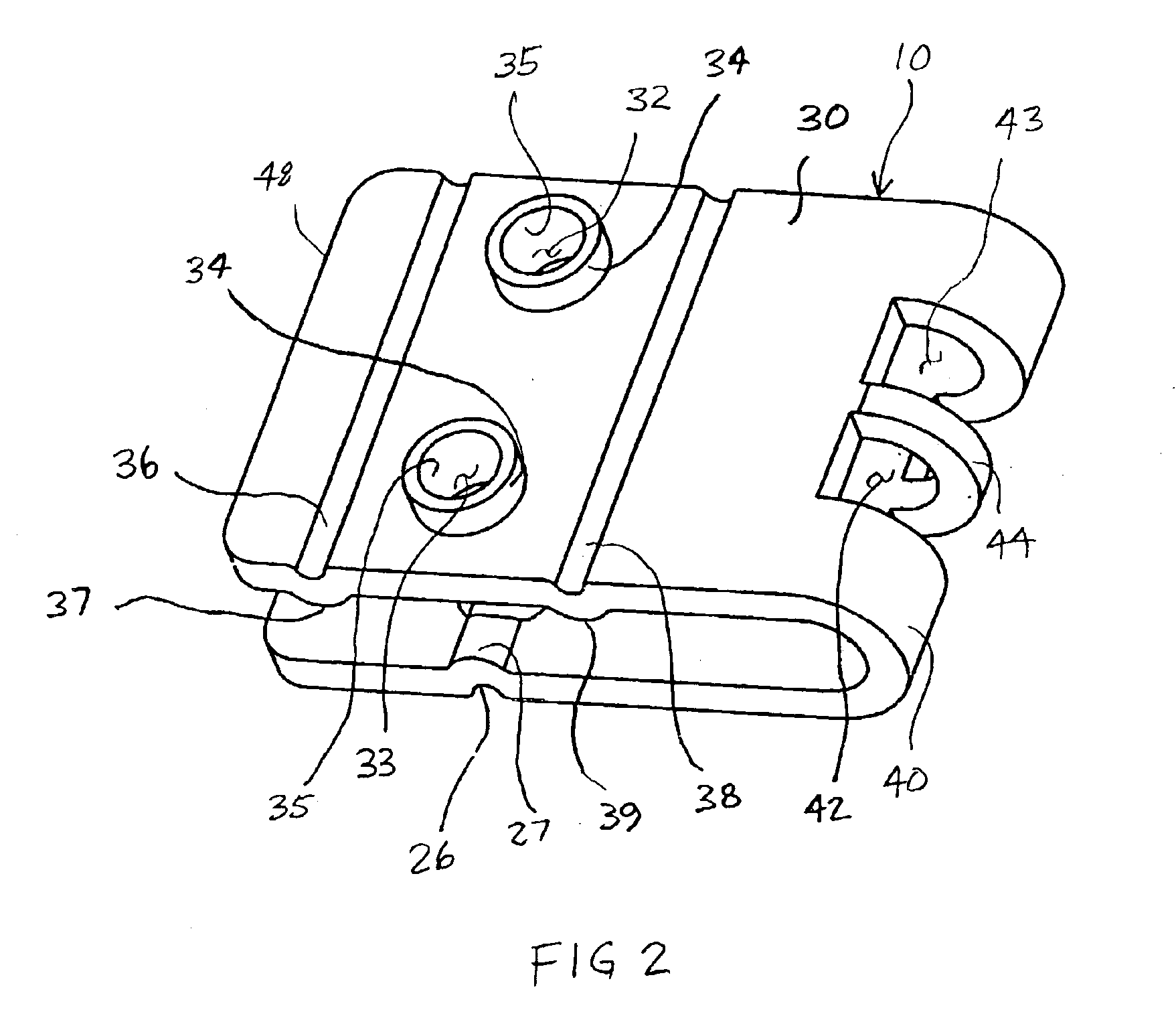
Referring to the Figures, the wire rope clamp 10 of the present invention includes a first plate portion 20 and a second plate portion 30 which are connected together by a central fold 40. The first plate portion 20 is spaced apart from second plate portion 30 to provide a sufficient gap to allow for the insertion of one or more wire ropes between the plates as will be hereinafter described. Preferably, first plate portion 20 and second plate portion 30 are generally parallel to one another.

The first plate portion 20 preferably includes a pair of spaced apart bolt holes 22 and 23. The bolt holes 22 and 23 are positioned along a bolt line 24 as shown in FIG. 1. The bolt line 24 is spaced from and parallel to the central fold 40. The first plate portion 20 also includes a first plate embossment 26 which extends from opposite sides 21 and 25 of first plate portion 20 and is parallel to the central fold 40. The embossment 26 creates a crest 27 on an inner surface of the first plate port...


PUM


Abstract

A wire rope clamp includes a U-shaped clamp member having a central fold. The clamp member has a first plate portion on one end of the central fold and a second plate portion on an opposite end of the central fold. The clamp member has a least one opening therein sized to allow at least one wire rope to pass therethrough. Such opening is located on said central fold between opposite sides of the clamp member. A tightening member urges the first plate portion and the second plate portion relatively closer together causing the plate portions to clamp onto one or more wire ropes located therebetween. The plate portions have embossments perpendicular to the rope direction that provide sufficient clamping grip.

Description

BACKGROUND OF THE INVENTION1. Field of the InventionThe present invention relates to a wire rope clamp. More particularly, the present invention relates to a U-shaped clamp having a first plate portion and a second plate portion on opposite sides of a central fold which, when moved closer together, clamp onto a wire rope which passes through an opening in the central fold.2. Prior ArtA variety of wire rope clamps have been proposed. Perhaps the most common form of a wire rope clamp is a U-bolt and saddle combination. This device includes a U-bolt member of circular cross section with two parallel spaced apart threaded legs. A separate saddle member have openings to receive the legs is provided to straddle the two legs. The saddle is urged closer to the U end of the U-bolt member by tightening two nuts onto the threaded legs. Because the devices include four separate pieces, assembly may be difficult. Further, because of the circular cross section of the U-bolt member, a single conce...

Claims


Application Information

Patent Timeline
IPC IPC(8): F16G11/00F16G11/14F16G11/06
CPCF16G11/06F16G11/14Y10T24/44769Y10T24/3967Y10T24/44923Y10T403/5761Y10T24/3987Y10T24/3909Y10T403/7058Y10T24/3958
Inventor WARREN, ROBERT E.
Owner WARREN ROBERT E
Why Eureka
Try Eureka