Awning roller with internal motor

a technology of internal motors and rollers, applied in the field of rollers, can solve problems such as motors subject to potential damag

Inactive Publication Date: 2005-01-18
DOMETIC CORP
View PDF23 Cites 58 Cited by
  • Summary
  • Abstract
  • Description
  • Claims
  • Application Information

AI Technical Summary

Benefits of technology

The motor assembly also includes a transmission linkage fixably connected to the motor shaft, with the transmission linkage forming a plurality of notches corresponding to the plurality of projections of the tube. Each of the plurality of notches is for receiving one of the plurality of projections when the motor assembly is at least partially inserted into the tube. The transmission linkage rotates when the motor shaft is rotating, thereby causing the plurality of notches to engage the plurality of projections thereby causing the tube to rotate.
Further, if the awning is at least partially deployed, when the means for releasably connecting is released, the motor can freely rotate with the roll-up tube, whereby the spring biases the awning to retract into at least a mostly stowed position.
The motor assembly also includes a transmission linkage fixably connected to the motor shaft, with the transmission linkage forming at least three notches corresponding to the at least three projections of the tube, with each of the at least three notches for receiving one of the at least three projections of the tube when the motor assembly is at least partially inserted into the tube. The transmission linkage rotates when the motor shaft is rotating, causing the at least three notches to engage the at least three projections, thereby causing the tube to rotate.
The awning drive assembly comprising a motor assembly for at least partially inserting into the tube, with the motor assembly including a motor having a motor shaft extending from an end of the motor; and a transmission linkage connected to the motor shaft, the transmission linkage having at least as many fingers as there are slots, with each slot receiving a corresponding one of said fingers when the transmission linkage is inserted into the tube. The transmission linkage is rotated when the shaft is rotated when the motor is operated, thereby causing the tube to rotate for deploying or retracting the awning.
The motor assembly includes a motor having a motor shaft extending from an end of the motor; and a transmission linkage connected to the motor shaft. The transmission linkage forms one or more notches, wherein each of the projections is received by one of the notches when the transmission linkage is inserted into the tube. The transmission linkage rotates when the shaft is rotated when the motor is operated, thereby causing the tube to rotate for deploying or retracting the awning.

Problems solved by technology

This may expose the motor to the elements, and could lead to an awning that is either not as wide as it could be due to the width of the motor, or results in a motor that sticks out from the arm, making the motor subject to potential damage.
Further, the exterior motor can be aesthetically displeasing to the user.

Method used


Image

  • Awning roller with internal motor
  • Awning roller with internal motor
  • Awning roller with internal motor

Examples


Embodiment Construction

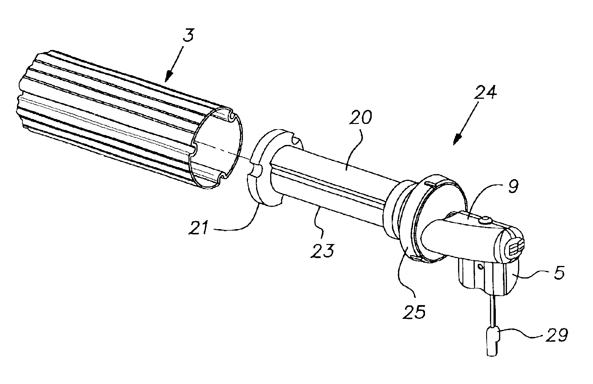
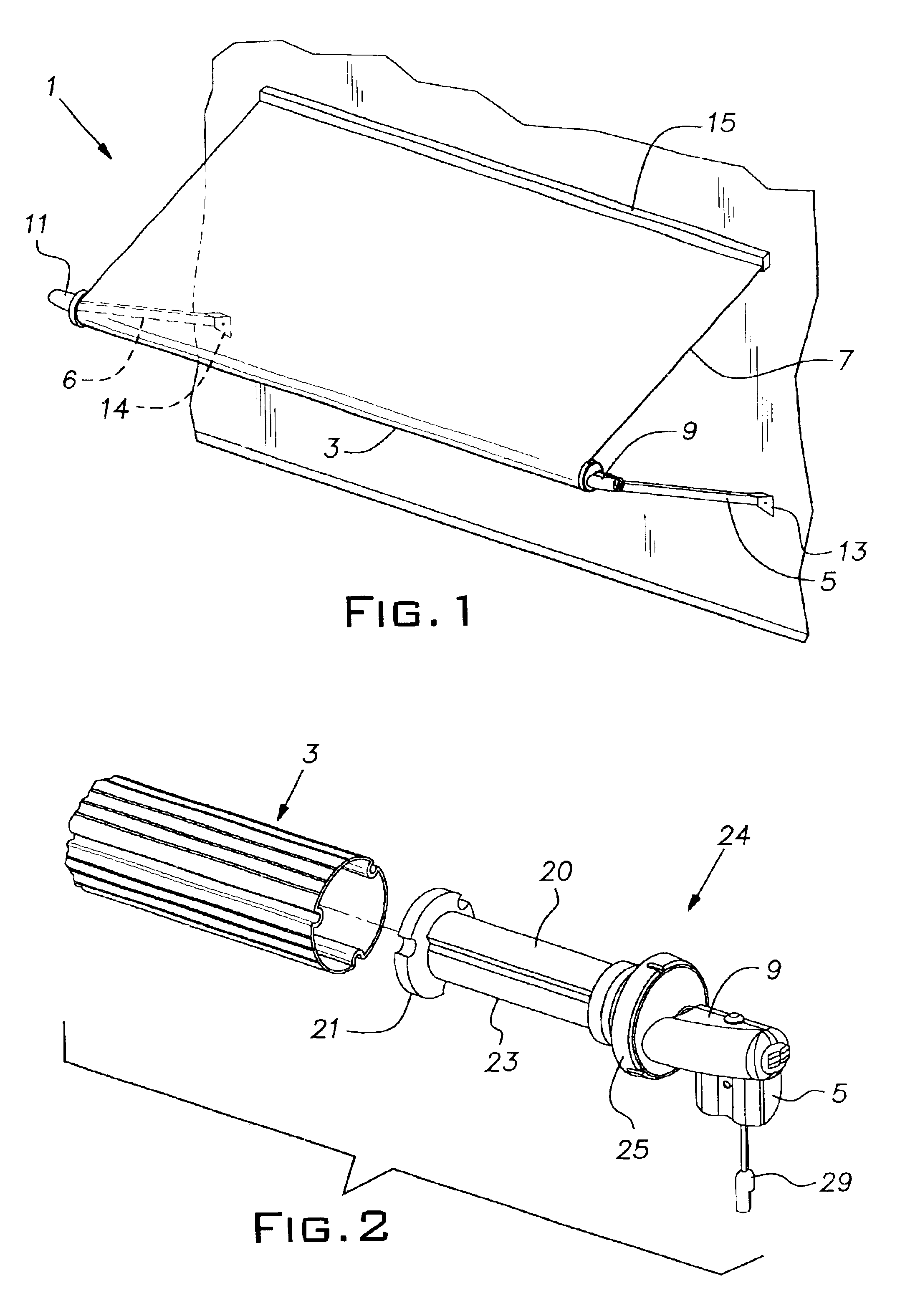
FIG. 1 shows one possible embodiment of the awning at least partially deployed. The awning has a canopy 7, rolled on and connected to a roll-up tube 3. The canopy is preferably waterproof, and typically will be at least partially opaque to provide sun protection. The awning has a roll-up tube 3 with a motor assembly at least partially inserted inside (not shown in FIG. 1), with the roll-up tube 3 connected to a support arm mounting assembly 9 at one end, and a support end 11 at another end.

The support arm mounting assembly 9 is typically connected to a support arm 5, for example, while the support end 11 is typically connected to a support arm 6, for example. The support arms are typically connected to the wall of a house or vehicle via wall mounts 13, 14. The canopy is also typically connected to the wall via a canopy mount 15. Alternative methods of mounting the awning are also well known in the art, and are easily accommodated by the invention.

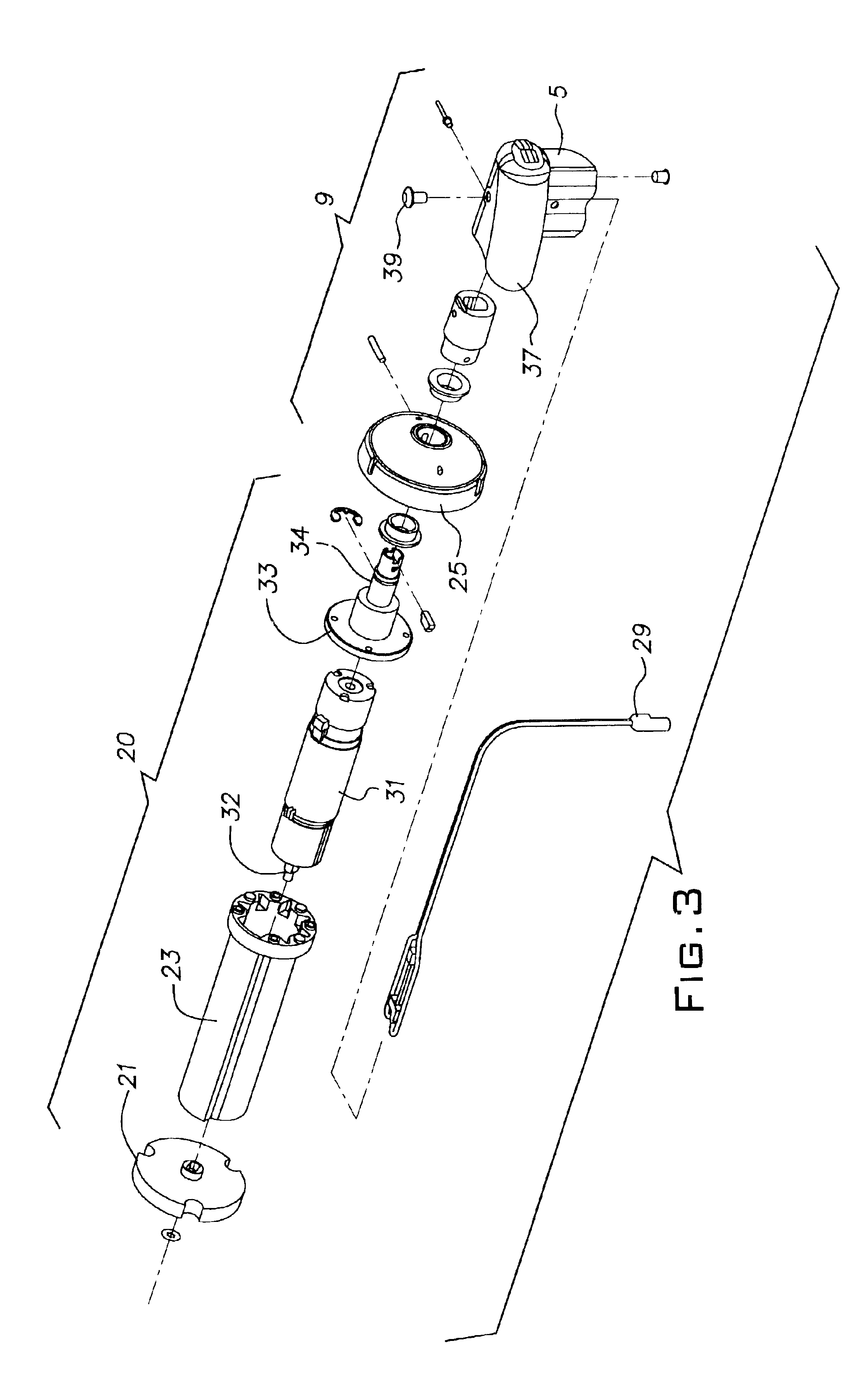
FIG. 2 shows the motor assembly 20 a...


PUM


Abstract

An awning drive assembly with a motor internal to an awning roll-up tube and / or the awning using the awning drive assembly. A transmission linkage is attached to a motor assembly which is at least partially inserted into the roll-up tube of the awning. The transmission linkage is a disk connected to a motor shaft and the disk has notches which engage corresponding projections within the roll-up tube, allowing the motor to deploy and retract the awning. The awning drive assembly also has a mechanism for releasably connecting the motor assembly to a support arm mounting assembly. When the means for releasably connecting is released, a spring retracts the awning, even when the motor is not operable.

Description

BACKGROUND OF THE INVENTIONThis invention relates generally to roll-up awnings, and in particular to awnings used for buildings, travel trailers, or recreational vehicles, and specifically to an awning roller assembly with a motor embedded within a roll-up tube for deploying and retracting the awning.It has long been recognized that roll-up awnings are useful in the recreational vehicle field. Such awnings are particularly useful when trailer homes or recreational vehicles are parked at a campsite. While parked, there is a need for a protected area in which users may take cover from inclement weather. A spring-biased, roll-up awning has long been used in the field.A roll-up, retractable awning generally comprises a canopy connected at one edge to the wall of a building or recreational vehicle, and at the opposite edge connected to a roller tube. The roller tube is pivotally supported by extended arms which are pivotally mounted to the wall. In a stored position, the canopy is rolled...

Claims


Application Information

Patent Timeline
Patent Type & Authority Patents(United States)
IPC IPC(8): E04F10/00E04F10/06E06B9/72E06B9/68
CPCE04F10/0614E06B9/72E04F10/0648E04F10/0625
Inventor CARRILLO, ALEJANDROWAGNER, BRENTLOZITO, THOMAS
Owner DOMETIC CORP
Why Eureka
Try Eureka