Flying toy

a flying toy and toy technology, applied in the field of toys, can solve the problems of a great deal of effort in the following prior art to eliminate or counteract the torque created by horizontal rotating propellers

Inactive Publication Date: 2005-01-18
DAVIS STEVEN
View PDF42 Cites 61 Cited by
  • Summary
  • Abstract
  • Description
  • Claims
  • Application Information

AI Technical Summary

Benefits of technology

In accordance with the present invention a self-stabilizing rotating flying toy that includes a main rotor is attached to a main body with a plurality of blades fixed with respect to the main body. The blades and main body rotate in a opposite direction caused by the torque of a motor mechanism used to rotate the main rotor positioned below the blades. The blades extend from a inner hub to an outer ring. The main hub connected above the inner hub is positioned above the blades and main body such that the Center of Gravity is above the center of lift, to provide a self-stabilizing rotating toy.

Problems solved by technology

However, a great deal of effort is made in the following prior art to eliminate or counteract the torque created by horizontal rotating propellers in flying aircraft in order to replace increased stability by removing gyro-stabilization systems.

Method used


Image

  • Flying toy
  • Flying toy
  • Flying toy

Examples


Embodiment Construction

While the invention is susceptible to embodiments in many different forms, there are shown in the drawings and will be described herein, in detail, the preferred embodiments of the present invention. It should be understood, however, that the present disclosure is to be considered an exemplification of the principles of the invention and is not intended to limit the spirit or scope of the invention and / or claims of the embodiments illustrated.

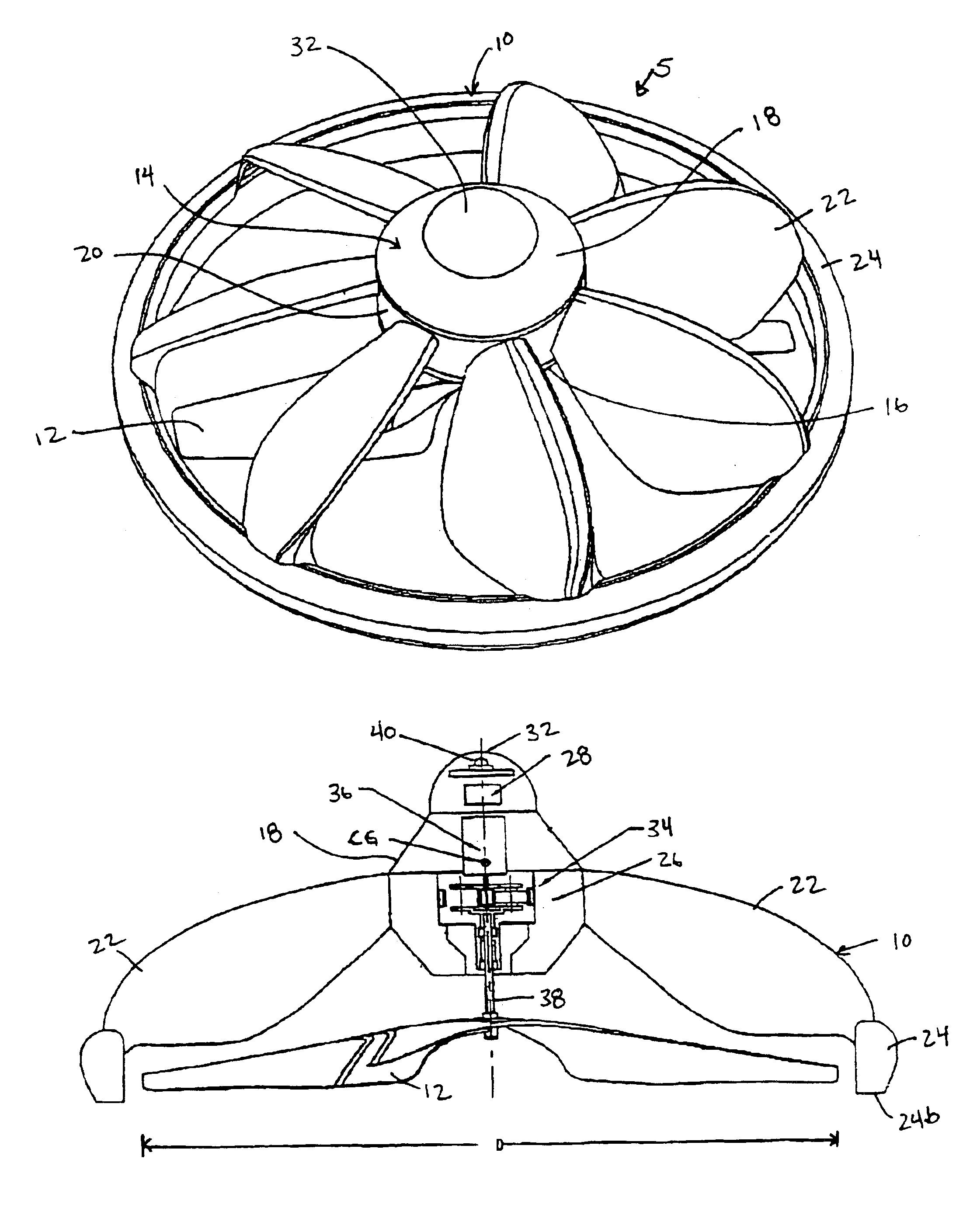
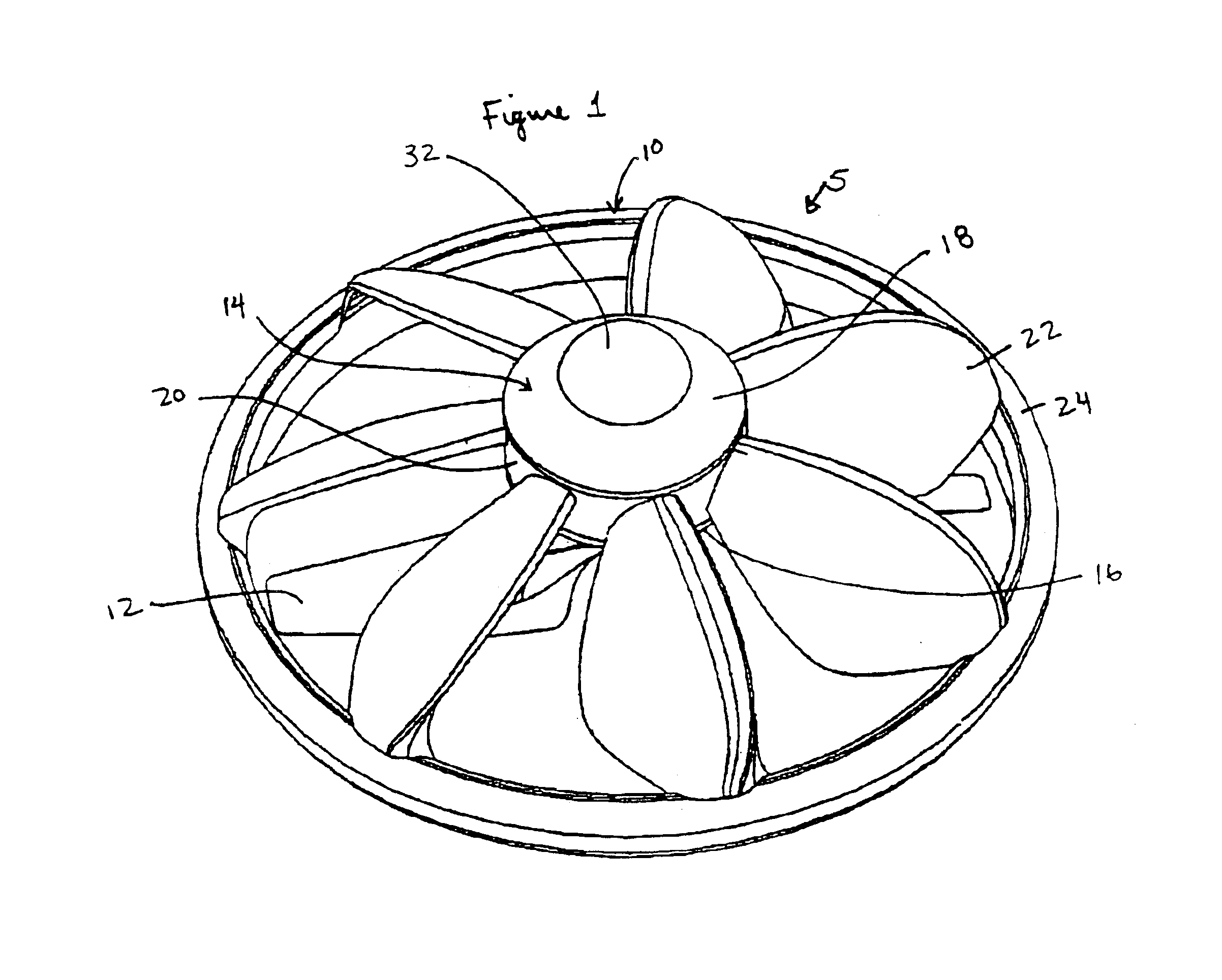
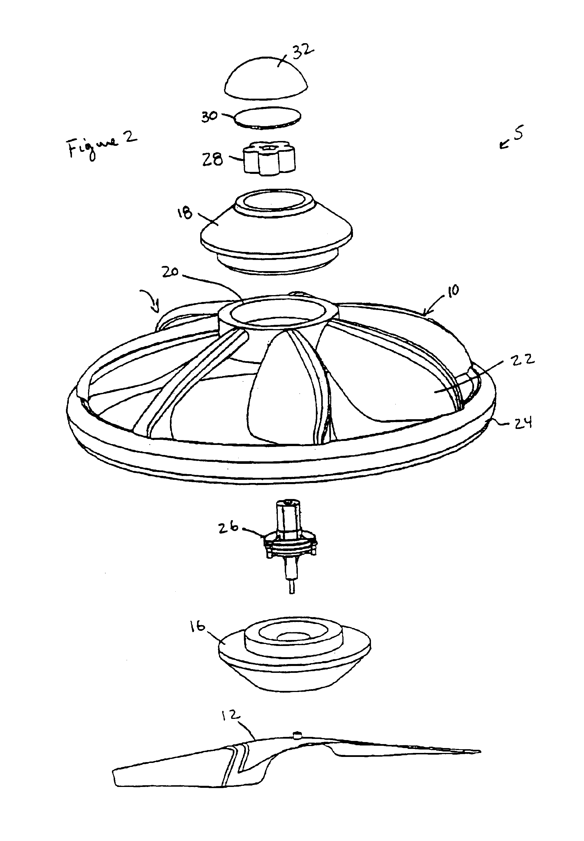
Referring to FIGS. 1 and 2, in a first embodiment of the present invention a flying rotating toy 5 is provided. The rotating toy 5 includes a single main rotor 12 rotatably attached to a light weight counter rotating main body 10. The counter rotating main body 10 includes a hub 14 that contains the drive and control mechanisms. The hub 14 is defined as having a lower hub section 16 and an upper hub section 18 that are received by an inner hub 20. A plurality of blades 22 extend outwardly and downwardly from the hub 14 to an outer ring 24. The ...


PUM


Abstract

A rotating toy may then include a hub having a central axis and a lower portion; a plurality of counter rotating blades extending outwardly from the lower portion of the hub, the plurality of counter rotating blades having a tip connected to an outer ring; a single means for rotating the hub and blades sufficiently quickly to generate a major portion of the lift generated by the aircraft through the single rotating means; and the hub having an upper portion above the plurality of counter rotating blades and above the single rotating means such that the aircraft includes a center of gravity above the plurality of counter rotating blades to provide a self-stabilizing rotating toy. In furtherance thereto the single rotating means may be secured on the central axis and positioned below the counter rotating blades.

Description

FIELD OF THE INVENTIONThis invention relates generally to toys and more particularly to directionally uncontrollable self-stabilizing rotating toys.BACKGROUND OF THE INVENTIONMost vertical takeoff and landing aircraft rely on gyro stabilization systems to remain stable in hovering flight. For instance, applicant's previous U.S. Pat. No. 5,971,320 and International PCT application WO 99 / 10235 discloses a helicopter with a gyroscopic rotor assembly. The helicopter disclosed therein uses a yaw propeller mounted on the frame of the body to control the orientation or yaw of the helicopter. However, different characteristics are present when the body of the toy, such as a flying saucer model, rotates as gyro stabilization systems may not be necessary when the body rotates, for example, see U.S. Pat. Nos. 5,297,759; 5,634,839; 5,672,086; and co-pending co-assigned U.S. patent application Ser. No. 09 / 819,189.However, a great deal of effort is made in the following prior art to eliminate or ...

Claims


Application Information

Patent Timeline
Patent Type & Authority Patents(United States)
IPC IPC(8): A63H27/04A63H33/00A63H30/00A63H33/18A63H30/04A63H27/00A63H1/00A63H27/127B64C27/00
CPCA63H27/04A63H33/18A63H30/04A63H27/12
Inventor DAVIS, STEVEN
Owner DAVIS STEVEN
Why Eureka
Try Eureka