
Thermal insulating window and entrance portable cover/pad

a technology of thermal insulation and portable covers, applied in the direction of door/window protective devices, curtain rods, special door/window arrangements, etc., can solve the problems of reducing the efficiency of the furnace, requiring a greater increase in fuel consumption, and the method will have little if any

Inactive Publication Date: 2005-02-01
THOMAS DONALD LEE
View PDF25 Cites 49 Cited by
  • Summary
  • Abstract
  • Description
  • Claims
  • Application Information

AI Technical Summary

Benefits of technology

A need for a long period of time has existed for a portable window insulating system that is simple and cost effective to install at first application, which will not alter the current window or entrance framing.
An important object of the present invention is to enable a person to remove the cover from the window framing is a simple manner.
During cold weather months the present invention, when installed inside a dwelling, will greatly restrict warm air and radiant heat from escaping between small crevices in inept window systems by fitting firmly into window framing using an insulating material.
This lightweight portable and removable insulating cover is placed over the interior-side generally (or the exterior) of typical commercial and residential building windows and entrances, providing added thermal protection inside of the dwelling, whereby creating a thermal barrier.
It is still another object of this invention to provide a complete window assembly that is simple, reusable, easy and economical to maintain.

Problems solved by technology

This method does offer some thermal insulation properties; however, in older dwellings with inept windows and entrances this method will have very little if any effect.
In addition this application has problems with condensation build-up when in use.
In cold weather months if a furnace is used to heat the dwelling, the produced warm air will rapidly escape through the drafty windows making it uncomfortable and thereby lowering the efficiency of the furnace or requiring a greater increase in fuel consumption to warrant eliminating the problem.
These methods listed above are known to suffer from the following disadvantages:a) poor thermal protections during cold weather months, by permitting warm air to escape between small crevices in inept window systems;(b) neither system is designed to have an insulating layer fit firmly inside the window framing while utilizing surrounding wall element for fastening without altering the window and / or framing itself.

Method used


Image

  • Thermal insulating window and entrance portable cover/pad
  • Thermal insulating window and entrance portable cover/pad
  • Thermal insulating window and entrance portable cover/pad

Examples


Embodiment Construction

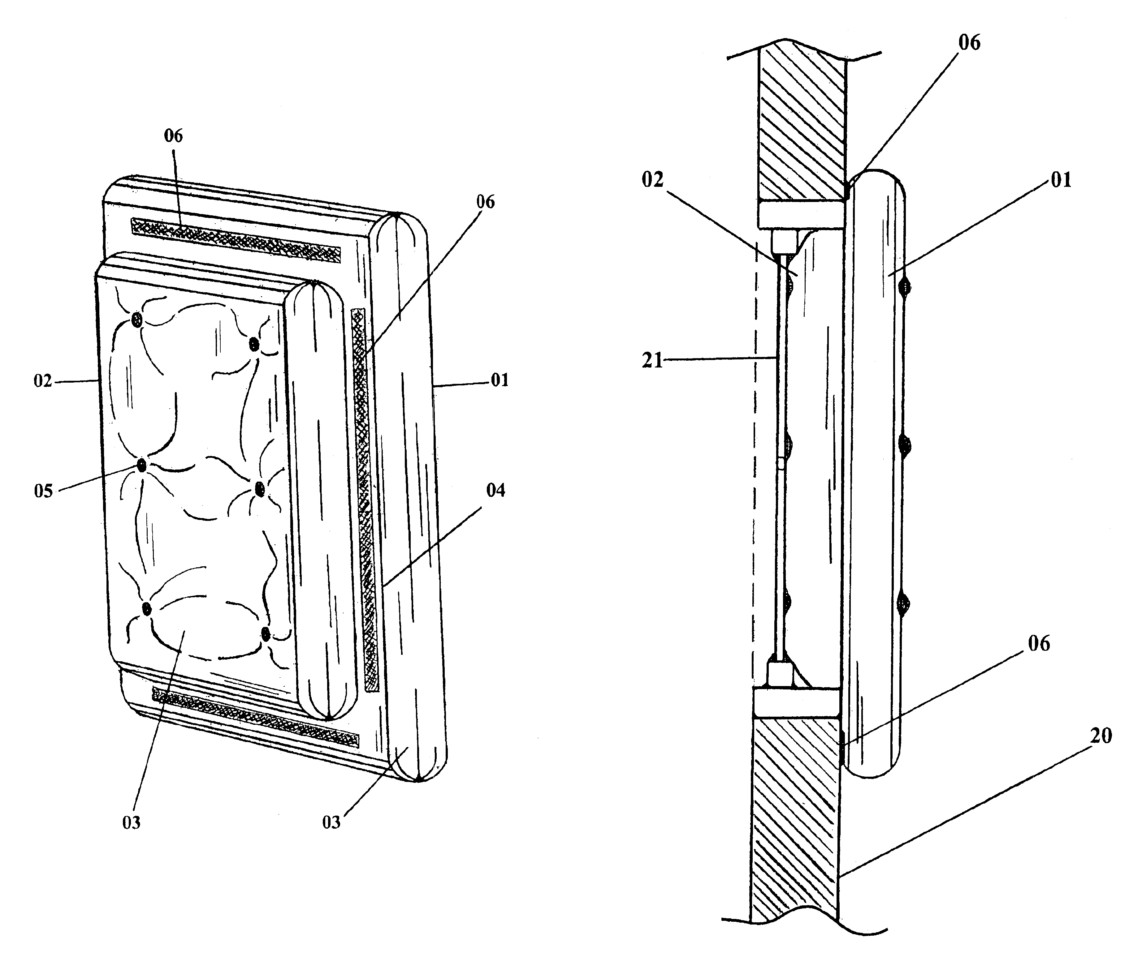
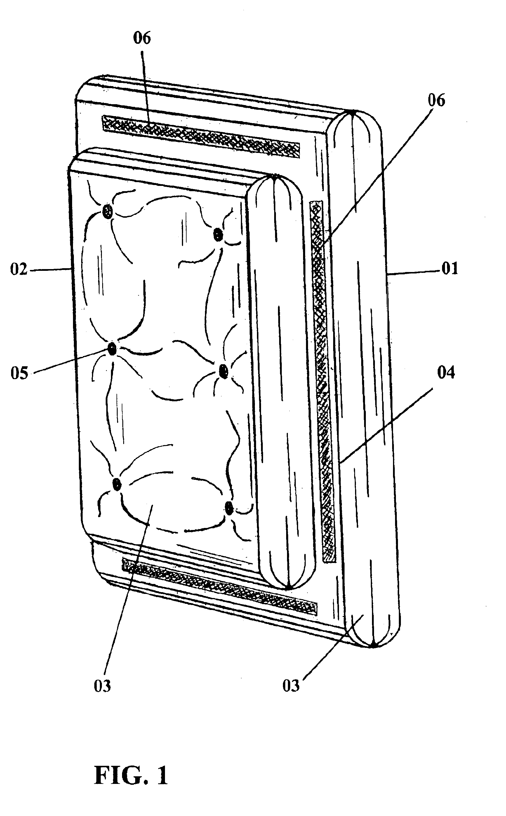
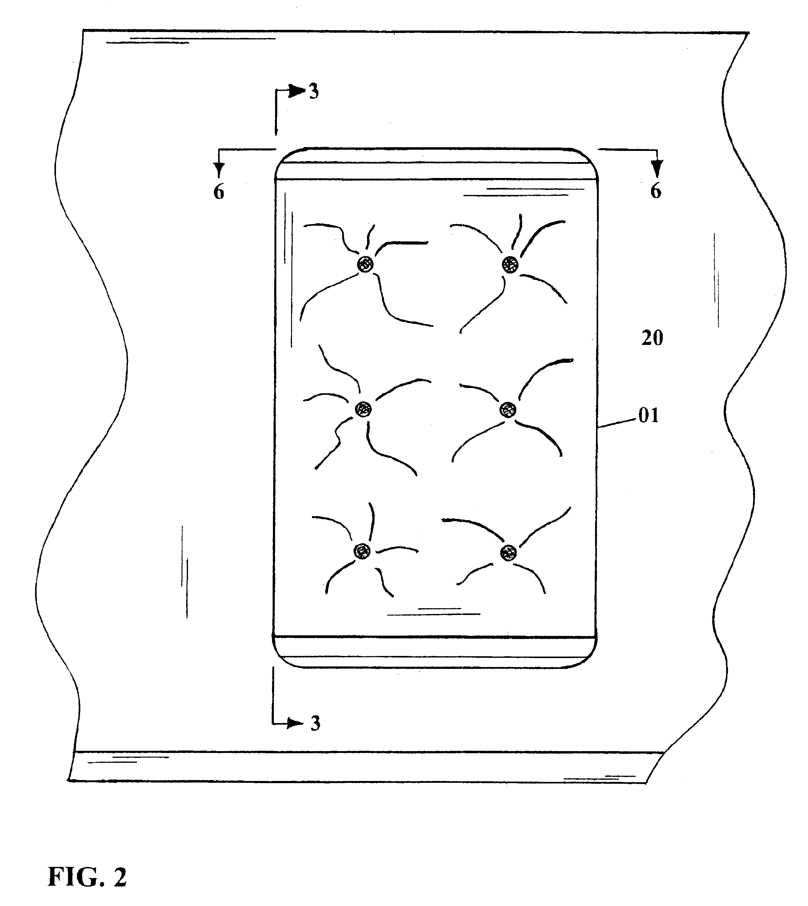
FIG. 1 shows the portable insulation device of the present invention. Shown in this view is an insulating core-element fabricated utilizing two functional sections which are the outer portion attachment pad section 01 and the inner portion insert pad section 02. Both the outer and inner portions or pads are illustrated here as completely and individually encased in a fabric material 03. As illustrated, the outer portion attachment pad section 01 is larger than the inner portion insert pad section in at least two dimensions, namely for example in height and width as viewed. Thus the attachment pad section effectively overlaps the insert pad section, and on this overlap segment are shown fasteners as will be further described herebelow. Said inner portion insert pad section is seen to protrude or jut out from the outer portion attachment pad section. All seams, corners, and edges of the fabric material 03 are bound together using heavy-duty nylon threading material 04. Spaced uniforml...


PUM


Abstract

An inexpensive, lightweight, reusable and detachable or removable insulation device for residential and commercial dwellings and similar heated structures. The device has an inner-portion insulating pad adapted to fit inside of a typical entrance or window unit framing. The device further has an outer-portion insulating pad adapted to overlap the window or entrance framing. The outer-portion insulating pad is provided fasteners so as to be secured to the building wall structure outside of the framing and surrounding the window or entrance framing by. During cold weather months, the present invention will greatly restrict warm air from escaping between small crevices in inept window systems by fitting firmly into window framing using a insulating material, thus creating a thermal barrier and improving the efficiency of the furnace by reducing the demand for electricity or fuel consumption.

Description

BACKGROUND1. Field of InventionThis invention relates to detachable insulating covers that are particularly suited for use in connection with windows and entrances of residential and commercial dwellings.2. Prior ArtIt is known from prior art that heat transfer through the windows and entrances of residential and commercial dwellings can be greatly reduced through the use of insulating covers.Prior art has shown application of thin sheets of transparent plastic material and the like affixed to the windows and entrances. This method does offer some thermal insulation properties; however, in older dwellings with inept windows and entrances this method will have very little if any effect. In addition this application has problems with condensation build-up when in use.Another solution of prior art in U.S. Pat. No. 4,610,292 (1986) suggested the use of insulated window shades and curtains. In this method window shades have a separate or detachable insulating layer behind the cloth fabri...

Claims


Application Information

Patent Timeline
IPC IPC(8): E06B7/00E06B3/28E06B3/04E06B9/24E06B7/28
CPCE06B3/28E06B9/24E06B7/28
Inventor THOMAS, DONALD LEE
Owner THOMAS DONALD LEE
Learn More