
Portable photovoltaic window system

a photovoltaic and window system technology, applied in photovoltaic supports, power plants, sustainable buildings, etc., can solve the problems of not being able to be easily removed, changed and/or upgraded, and still a permanently mounted feature, etc., to achieve the effect of simple and cost-effective installation

Inactive Publication Date: 2009-06-04
THOMAS DONALD LEE
View PDF10 Cites 29 Cited by
  • Summary
  • Abstract
  • Description
  • Claims
  • Application Information

AI Technical Summary

Benefits of technology

[0018]There has been a longstanding need for a portable building-integrated photovoltaic system that is both simple and cost effective to install at first application, and particularly one that does not damage or alter existing window, window framing or adjacent wall structures. The present invention provides a technique for generating solar power in existing buildings by using portable and removable fabric window coverings, an elastic cord lanyard array, hook fastener and / or suction cup attachment method / system to arrange solar panels in a position to best capture and convert solar energy from direct sunlight incidental to the location of the window itself.
[0019]Since the effectiveness of a solar collection panel is generally dependent upon its relative position to the sun, it is found that easy portability enables the user to selectively place the panel adjacent windows with more advantageous solar incidence. The present invention employs a lightweight and flexible fabric material which incorporates hook and loop fasteners (e.g., of the type available under the trade name Velcro®) and an elastic cord fastened around the perimeter of the fabric material. The hook and loop fasteners and elastic chord feature are used to secure the fabric material over the interior-side generally (or the exterior) of window units. A generally central portion of the fabric material incorporates sets of hook and loop fasteners employed in mounting at least one light weight solar panel.
[0021]An important object of the present invention is to offer a person with little knowledge of solar energy equipment a quick and simple method to convert sunlight into solar energy without making significant alterations to the building or window unit being used as a light-source.
[0022]Another important object of the present invention is that in event of power outages, this device could serve as a back-up source to deliver electric power where needed. In communities ruined by natural or man-made disasters, this device allows victims an easy and low-cost means to operate household electrical devices until regular power service is restored.
[0024]The present invention could be modified to incorporate thermal insulating material inside the layers of fabric window covering thus making the device a reusable dual energy conservation and alternative energy producing device.

Problems solved by technology

While Fronek provides an alternative to roof-mounted PV panel arrays, it is still a permanently mounted feature and not easily removed, changed and / or upgraded.
A major drawback of current solar applications is that they are expensive and permanently mounted roof-top structures, and with no emphasis placed on portability.
While this form of renewal energy has promise, it requires open spaces of land and tall wind vane columns, clearly not feasible for portable and emergency energy production purposes.
However, this particular solar powered unit is an item of relativity high cost and typical consumers would not be willing to make so high a capital investment for an item of such limited use.
Also, current BIPV units are not suited for portable, compact, lightweight micro-solar energy applications.
While Sundar's disclosure presents a portable solar design, it does not allow for the portable solar panel to be conveniently withdrawn and repositioned in other automobile windows by detaching and relocating the solar panel.
Thus, the scope and use of Sundar's system is severely limited in this respect.
In addition, there is no suggestion that the Sundar device could be applied to various window openings in a building to supply electricity to any of a number of devices.

Method used


Image

  • Portable photovoltaic window system
  • Portable photovoltaic window system
  • Portable photovoltaic window system

Examples


Embodiment Construction

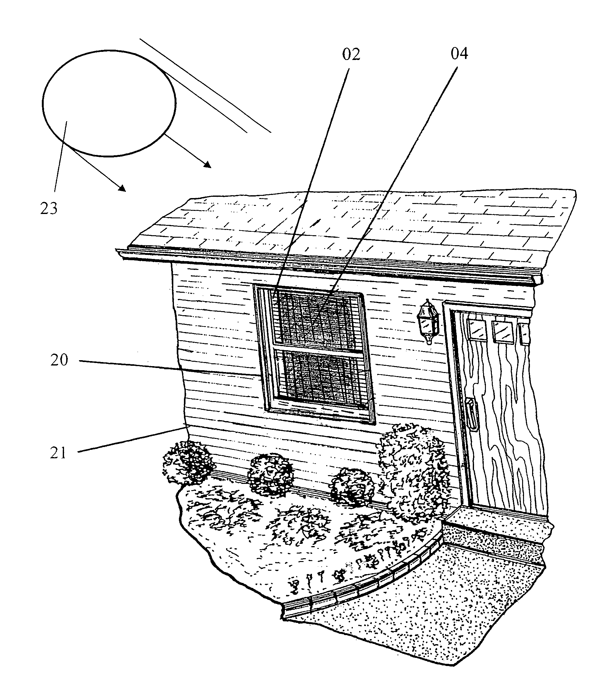
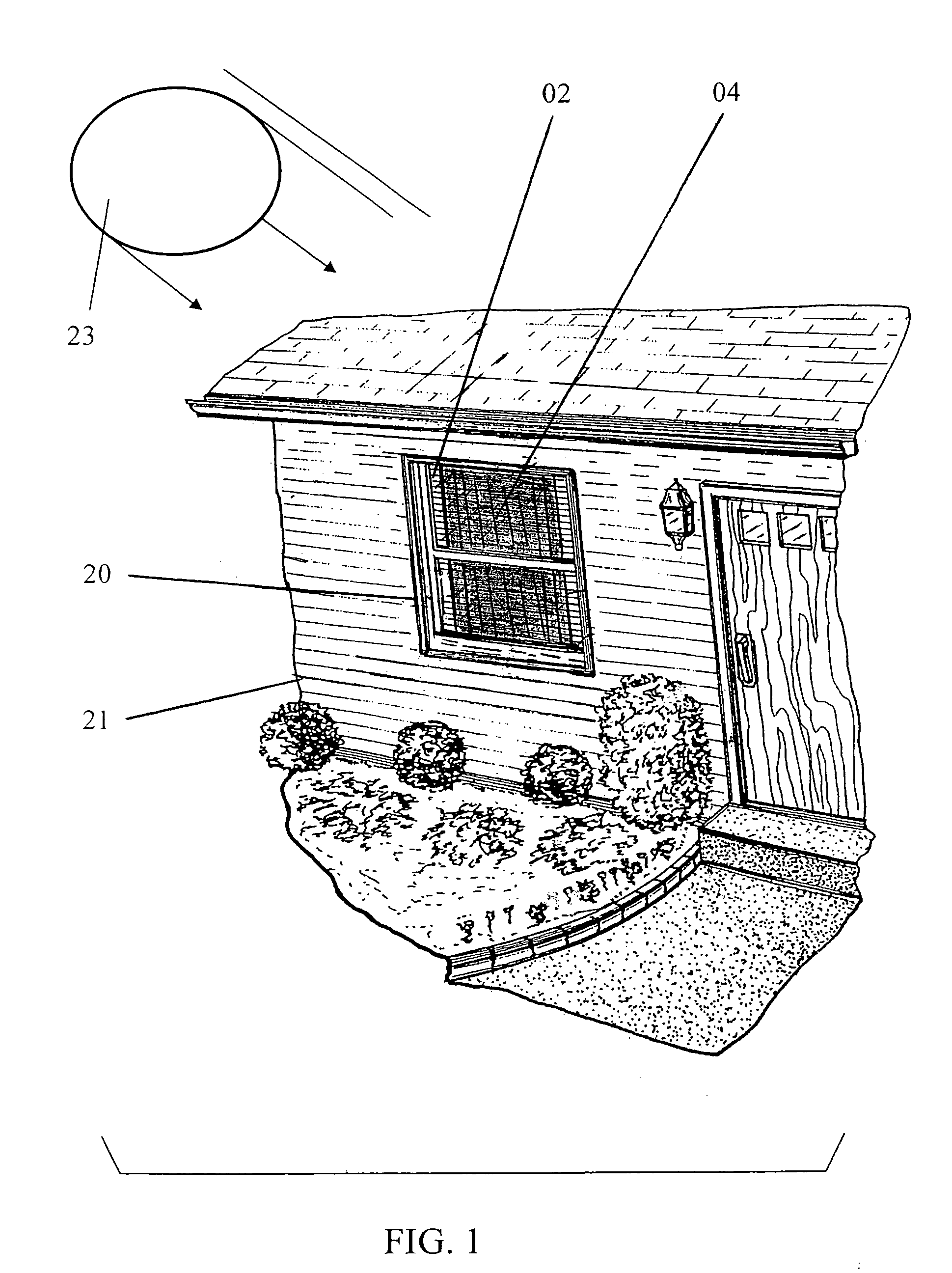
[0045]Illustrated in FIG. 1 is a perspective view of an exterior house or building structure 21 with the present invention installed. In this (FIG. 1) illustration the present invention is installed on the interior side of window unit 20 depicted as positioned within an opening defined in a house or building wall 22. This installation is fully illustrated in FIG. 6. The solar panel 04 is attached to the fabric window covering 01 and positioned in a manner to convert solar energy from direct sunlight incidental to the location of the window unit 20 itself.

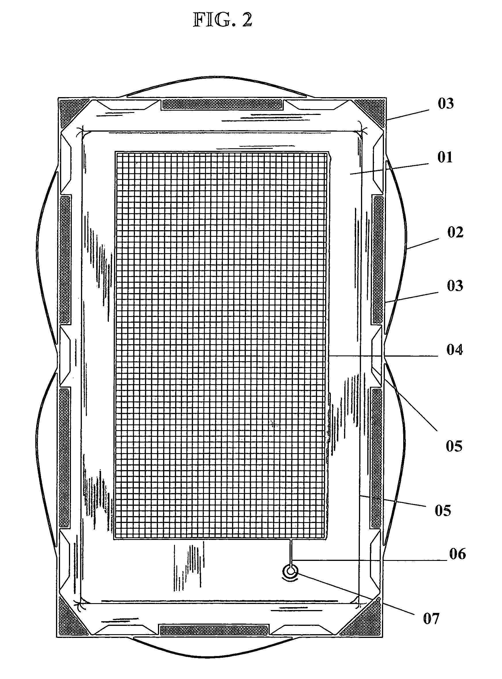
[0046]An elevation view depicted in FIG. 2 shows the front or outward window-facing side of the present invention with the solar panel unit 04 installed. Shown in this view is a fabric window covering 01 used as a mounting support for an installed solar panel unit 04. The solar panel unit 04 is centered on said fabric window covering 01 in a manner that when installed the solar panel unit is located facing (outwardly toward) direct ...


PUM


Abstract

A portable, lightweight and detachable photovoltaic window system affording a resource for converting solar power in existing buildings and similar structures. At least one photovoltaic panel is interconnected to a building window or entrance casing or directly to a window pane through use of lanyards, hook and loop fasteners, or suction cups. Solar energy is captured from direct sunlight incidental to the location of the window. A panel may be removably supported by a fabric material interconnected to an interior wall via hook and loop fasteners. An inverter converts energy from DC to AC for powering electrically driven devices. A pocket is provided on the panel support for temporarily storing the auxiliary devices. This system enables a person with little knowledge of solar energy equipment a convenient and inexpensive method to convert sunlight into useful energy without major alterations to the building or window unit being used as a light-source.

Description

CROSS-REFERENCE TO RELATED APPLICATIONS[0001]All priority benefits under 35 USC 119(e) of Provisional Patent Application Ser. No. 61 / 005,021 filed Dec. 3, 2007 are hereby claimed and the contents thereof in their entirety incorporated herein by reference. The present invention is the subject matter of a Disclosure Document filed in the United States Patent and Trademark Office on Aug. 4, 2006 and registered as No. 604318. All benefits of said registered Disclosure Document are claimed under 35 U.S.C. Section 122, 37 C.F.R. Section 1.14, and MPEP section 1706. The present application also is related to applicant's application Ser. No. 10 / 241,855 filed Sep. 13, 2002, which was published Mar. 18, 2004 as 2004 0050507, subsequently issued as U.S. Pat. No. 6,848,492 on Feb. 1, 2005, and the contents thereof in their entirety are hereby incorporated herein by reference.FEDERALLY SPONSORED RESEARCH[0002]Not ApplicableSEQUENCE LISTING[0003]Not Applicable.BACKGROUND OF THE INVENTION[0004]1. ...

Claims


Application Information

Patent Timeline
Patent Type & Authority Applications(United States)
IPC IPC(8): H01L31/042
CPCH01L31/042H02S20/00Y02E10/50Y02B10/14H02S30/10H02S10/40H02S20/20Y02B10/10
Inventor THOMAS, DONALD LEE
Owner THOMAS DONALD LEE
Learn More