Lighting fixture mounting system

Inactive Publication Date: 2005-02-01
LIGHTING PARTNERS JAX INC A FLORIDA CORP
View PDF5 Cites 6 Cited by
  • Summary
  • Abstract
  • Description
  • Claims
  • Application Information

AI Technical Summary

Problems solved by technology

In mounting fixtures to the ceiling or heavy wall mounted fixtures it is awkward for an installer to lift the light fixture while simultaneously performing the just described mounting task.

Method used


Image

  • Lighting fixture mounting system
  • Lighting fixture mounting system
  • Lighting fixture mounting system

Examples


Embodiment Construction

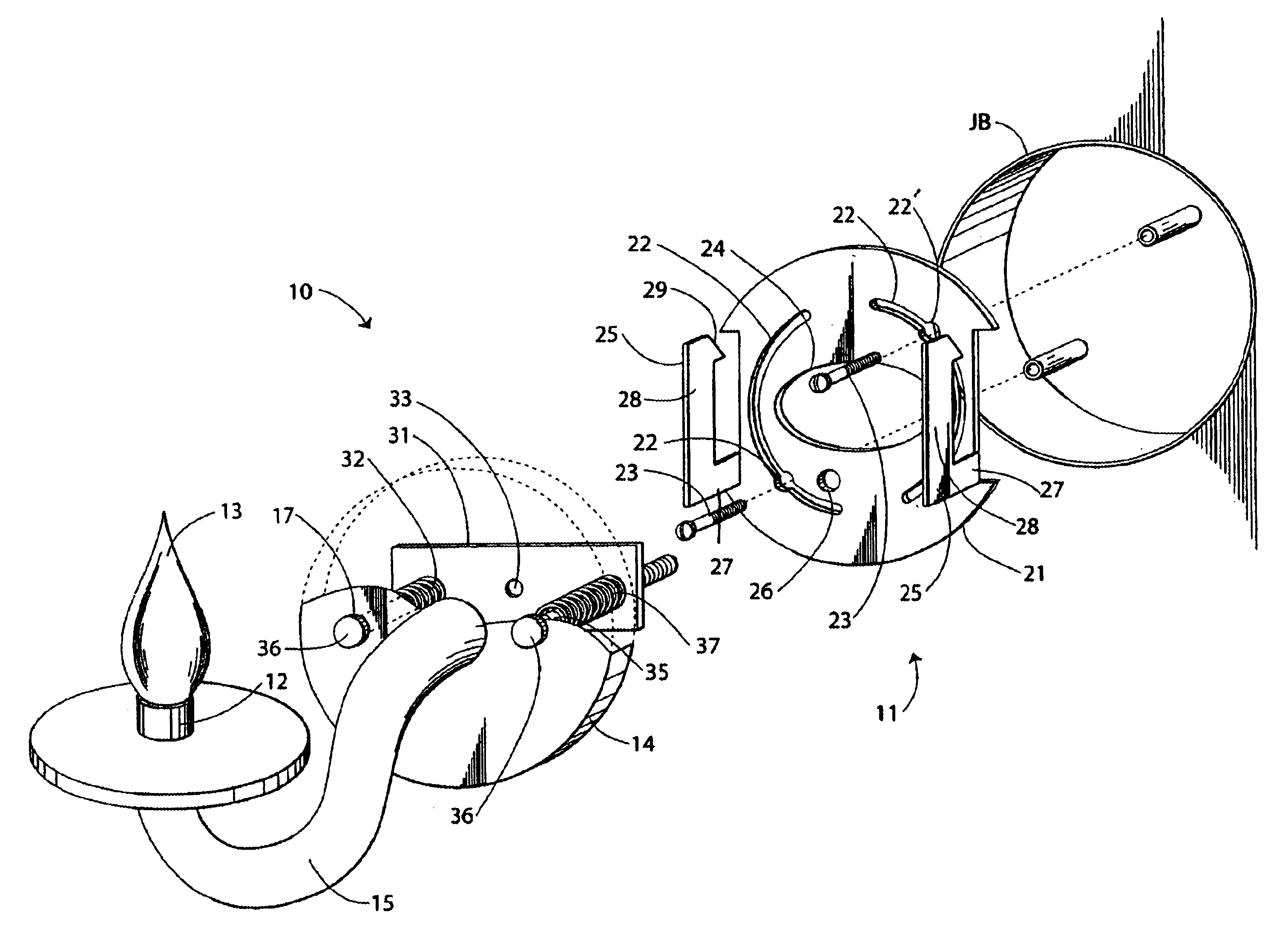
With reference next to the drawings, there is shown a light fixture 10 including a mounting system 11 embodying principles of the invention in a preferred form. The light fixture 10 is shown in the form of a wall mounted sconce, however, it should be understood that the present invention may be utilized with any type of light fixture, including but not limited to, ceiling fixtures, chandeliers, wall lights, and other devices such as ceiling fans.

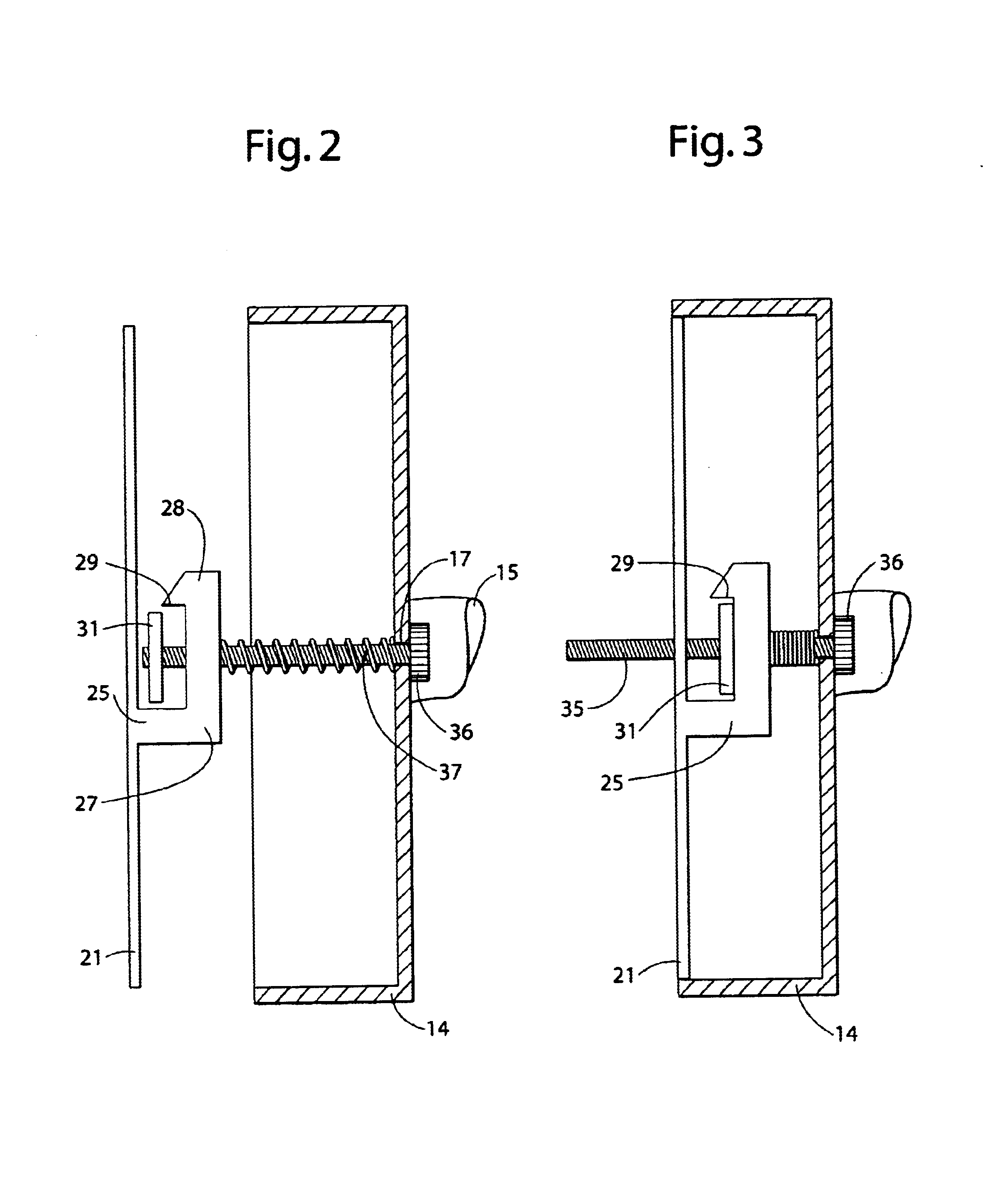
The light fixture 10 includes a light socket 12, a light bulb 13 mounted within the light socket 12, a cover plate 14 and an arm 15 extending between the cover plate 14 and the light socket 12. The cover plate 14 has a pair of post holes 17 therethrough.

The mounting system 11 also includes a mounting plate 21 having two arcuate mounting hole slots 22 having an enlarged portion 22′ therethrough through which mounting screws 23 extend and are threaded into the threaded receiving holes of a conventional junction box JB. The mounting plate 21 al...


PUM


Abstract

A light fixture mounting system (11) is disclosed having a cover plate (14) having a pair of post holes (17) therethrough, a mounting plate (21) has two, oppositely disposed peripheral hooks or catches (25), a latch bar (31), and two threaded posts (35). Each catch (25) has a horizontal portion (27) and a vertical portion (28) extending upwardly and terminating with a tang (29). The latch bar is coupled to the cover plate (14) for reciprocal movement between an engaged position distal the cover plate and a locked position proximal the cover plate. The latch bar (31) has two internally threaded adjustment holes (32) which are configured and threaded to receive two threaded posts (35) which extend through the cover plate post holes (17). Each post has a head portion (36) which may be configured to receive the drive end of a screwdriver or may be externally configured to enable one to grasp and rotate it with ease.

Description

TECHNICAL FIELDThis invention relates generally to lighting fixtures, and more particularly to the mounting systems for light fixtures.BACKGROUND OF THE INVENTIONLighting fixtures have existed for many years. These lighting fixtures may include chandeliers, ceiling lights, wall lights or sconces, and may include other systems such as ceiling fans which may include lights.Light fixtures are typically mounted to junction boxes that are recessed within a ceiling or wall and mounted to a joist or wall stud. During a conventional installation of a light fixture a mounting bar is coupled to the junction box through a pair of screws. The mounting bar has a centrally located internally threaded mounting hole in which is threadably mounted an externally threaded nipple. The nipple is passed through a control hole in the light fixture mounting plate and a threaded nut is threaded onto the nipple to secure the cover plate to the mounting bar. In mounting fixtures to the ceiling or heavy wall m...

Claims


Application Information

Patent Timeline
IPC IPC(8): F21V21/02F21V21/03
CPCF21V21/03
Inventor PATZ, JASON D.PAPE, ROBERT J.SIBSON, BRIAN S.
Owner LIGHTING PARTNERS JAX INC A FLORIDA CORP
Why Eureka
Try Eureka