
Method and apparatus for reproducing timing, and a demodulating apparatus that uses the method and apparatus for reproducing timing
a timing reproduction and demodulating apparatus technology, applied in the field of methods and apparatus for reproducing timing, can solve the problems that the demodulating apparatus for performing such timing reproduction operation cannot be applied in the wide-band radio communication system, and the sampling speed may exceed so as to achieve high precision and high speed, the effect of raising the maximum operating speed of the demodulating apparatus
- Summary
- Abstract
- Description
- Claims
- Application Information
AI Technical Summary
Benefits of technology
Problems solved by technology
Method used
Image



Examples
first embodiment
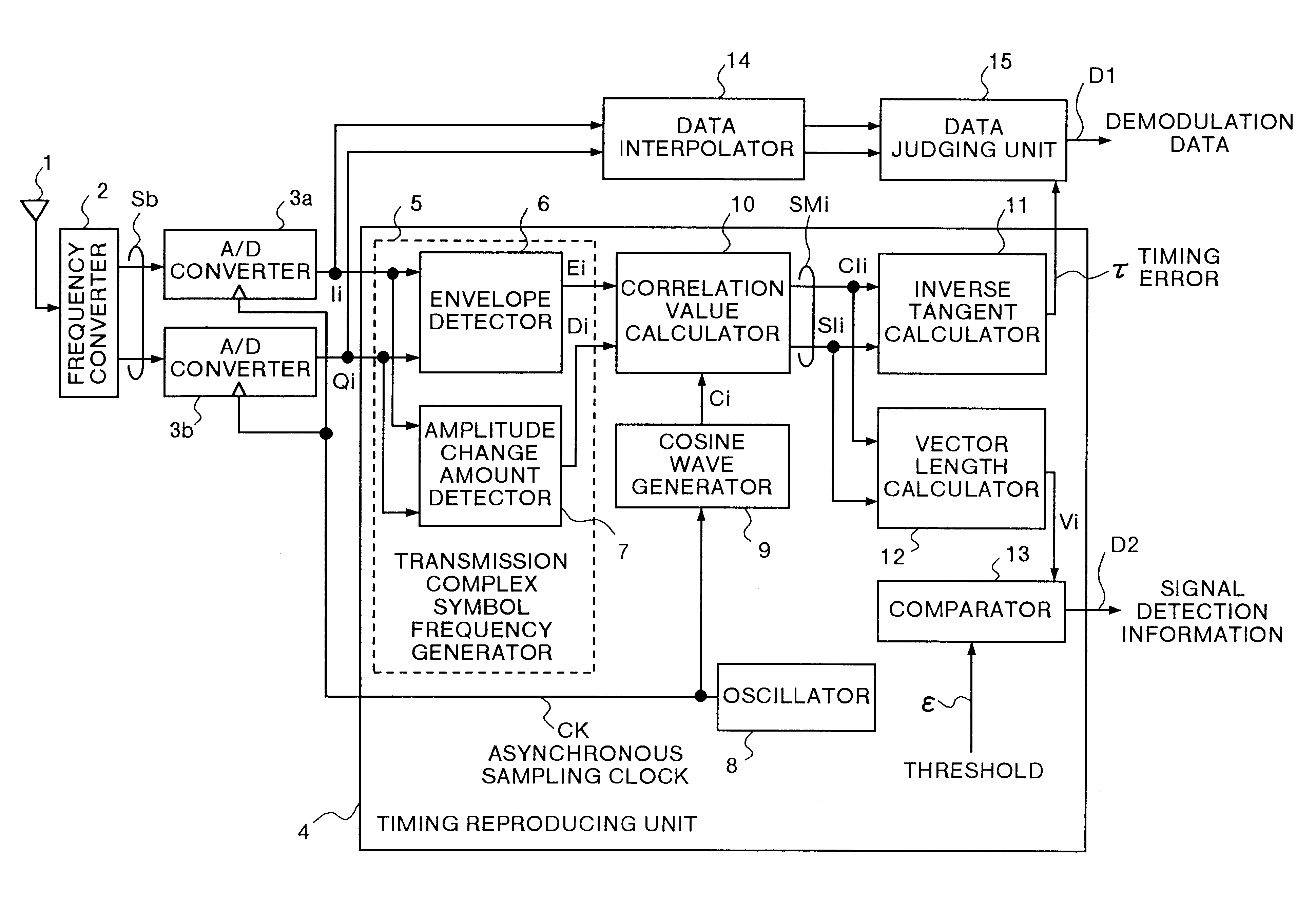
FIG. 1 is a block diagram showing a part of configuration of timing reproducing apparatus according to the invention. FIG. 1 also shows a receiver of a digital radio communication system that includes a modulating apparatus that uses the timing reproducing apparatus of the invention. An antenna 1 receives a burst signal in a PSK modulated RF (radio frequency) band. A frequency converter 2 converts the RF band reception signal entered from the antenna 1 into a base band signal (received base band signal Sb).
An A / D converter 3a, using an asynchronous sampling clock CK having a frequency of two (n=2) times of symbol rate issued from an oscillator 8, samples the received base band signal Sb at time t (=τ+iT / 2), and outputs the in-phase component of the sampled received base band signal Sb as in-phase data series Ii. Here, “i” is a natural number, “T” is a symbol period, and “τ” is a timing error (−T / 2≦τ<T / 2). Similarly, an A / D converter 3b, using an asynchronous sampling clock CK h...
second embodiment
the present invention will now be explained. In the foregoing first embodiment, it is assumed that the signal entered in the timing reproducing unit 4 is linearly controlled in level by an AGC (automatic gain control) amplifier, but in this second embodiment, whether the input signal in the timing reproducing unit 4 is linearly controlled in level by the AGC amplifier, or nonlinearly amplified at a constant level by a limiter amplifier, it is designed to estimate the timing error.
That is, in the first embodiment, the timing error τ was determined by using the envelope of reception base band and amplitude change amount, but in the case of hard-limited signal amplified nonlinearly at a constant level by an inexpensive limiter amplifier, the envelope presents a constant value, and fluctuations of symbol period as shown in FIG. 4 do not occur periodically, so that the timing reproducing unit 4 cannot estimate normal timing error. In the second embodiment, the timing reproducing unit 4 i...
PUM
 Abstract
Description
Claims
Application Information