Can opener

a can opener and man-operated technology, applied in the field of man-operable can openers, can solve the problem of difficulty for persons with weak grips to squeeze the handles together

Inactive Publication Date: 2005-02-08
UNION LUCKY IND LTD
View PDF9 Cites 14 Cited by
  • Summary
  • Abstract
  • Description
  • Claims
  • Application Information

AI Technical Summary

Problems solved by technology

Two problems with the above can opener are that the best position for holding the handles together is often not the most comfortable position for using the opener, and it can be difficult for persons with a weak grip to squeeze the handles together with sufficient force during operation of the can opener to properly engage the can rim between the cutter and traction wheel.

Method used


Image

  • Can opener
  • Can opener
  • Can opener

Examples


Embodiment Construction

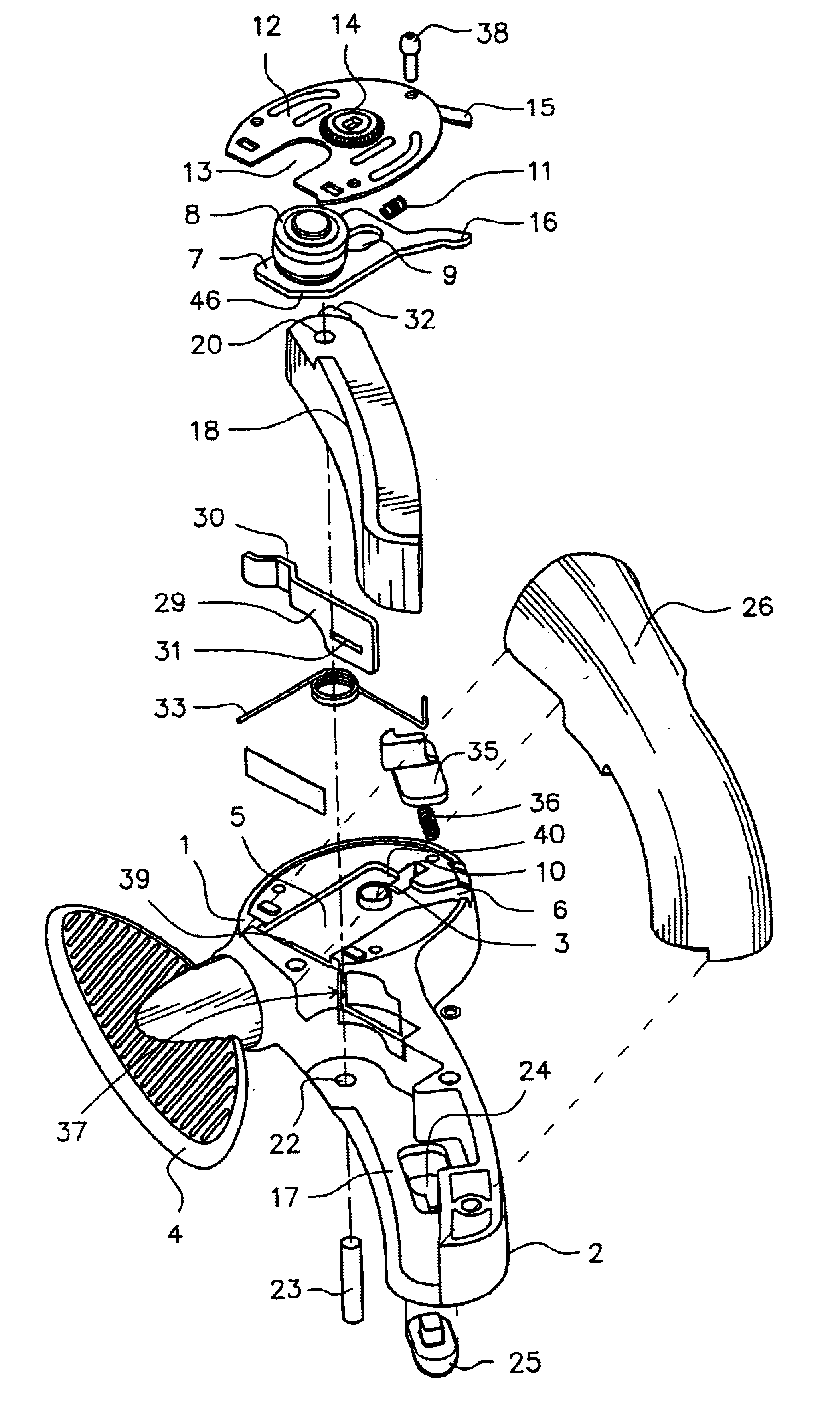
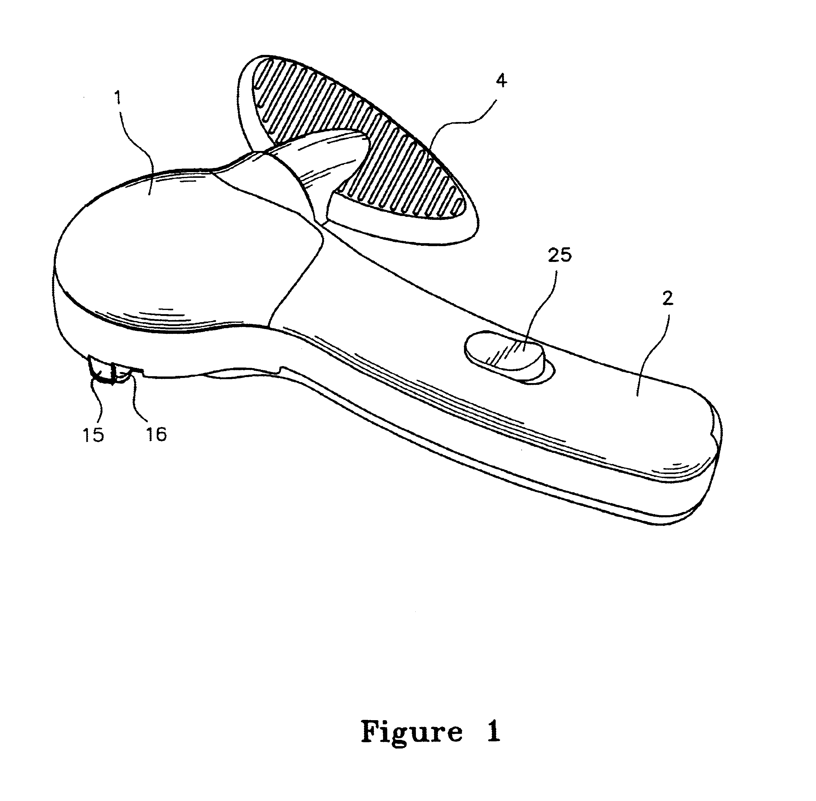
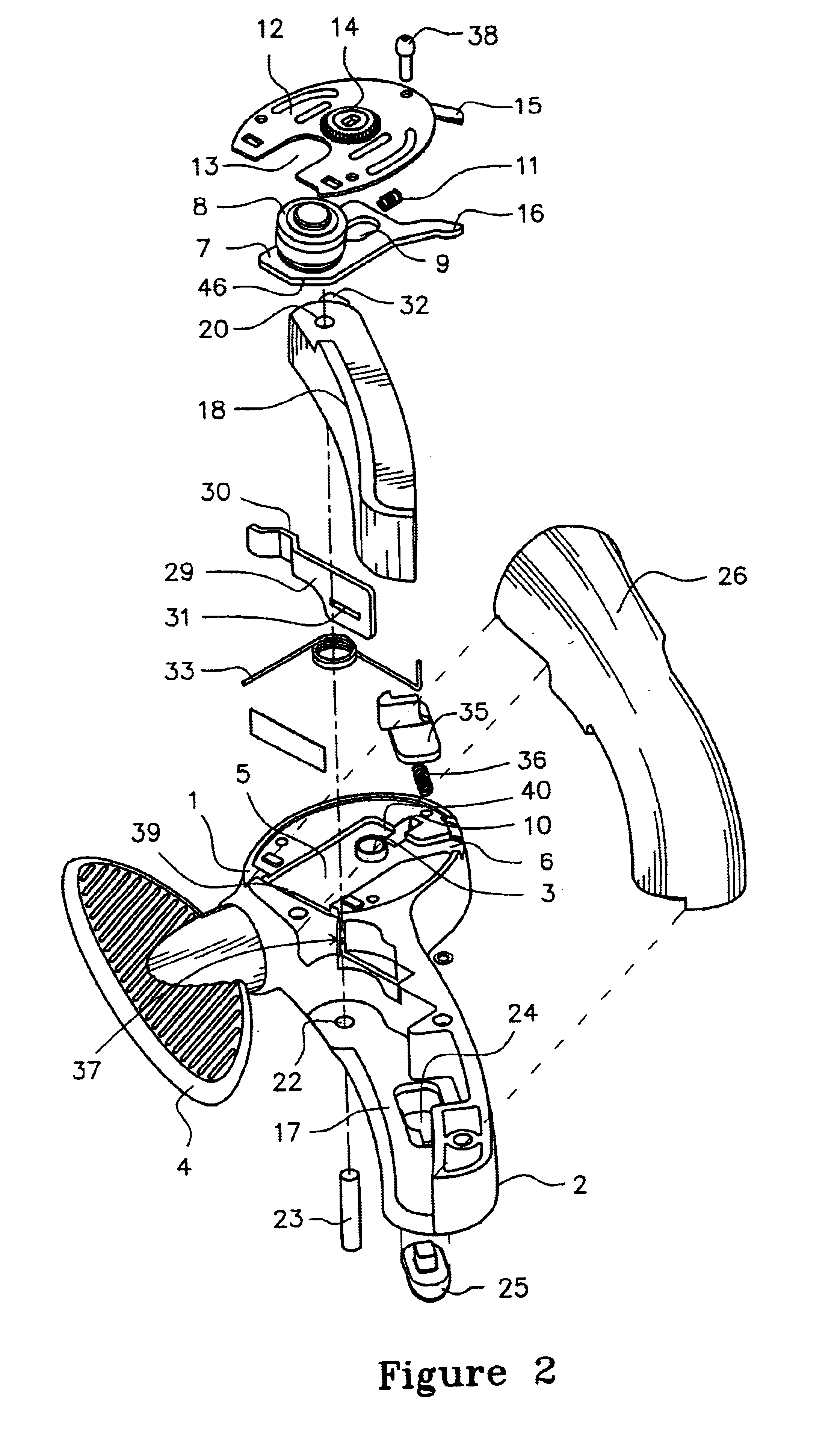
Referring to FIGS. 1 to 4, a can opener comprises a body portion 1 with an integrally formed handle 2 extending therefrom within the body 1 is a 90-degree gear with its output shaft 45 (not shown in FIG. 2) extending through an aperture 3 in the face of body 1. The input of the 90-degree gear is an operating handle 4 for manually operation of the output shaft 45. The output end of the output shaft 45 is keyed for engagement with a traction wheel 14.

The face of body 1 has a rectangular recess 5 with a channel 6 extending from a corner of the recess 5 to the edge of body 1. A rectangular carriage plate 7 locates within recess 5 The carriage plate 7 is longitudinally shorter than the recess 5 so that it can move longitudinally in the recess 5 from a first position proximate recess first end 39 to second position proximate recess second end 40. At recess second end 40 is a smaller cylindrical recess 10 that receives a spring 11 for biasing the carriage plate 7 in the first position.

A co...


PUM


Abstract

A can opener includes a body with a handle, a traction wheel rotatably mounted on the body, an operating element for turning the traction wheel, and a cutter. The cutter is moveable between an inoperative position for receiving a rim of a can between the traction wheel and cutter, and an operative position for engaging said rim of the can between the traction wheel and cutter. A cam with a lobe engages the cutter and moves it between the inoperative and operative positions. The cam is operated by a lever.

Description

BACKGROUND TO THE INVENTION1. Field of the InventionThe invention relates to manually operable can openers, and in particular to can openers of the laterally-cutting type2. Background InformationManually operable can openers have been known for many years and may be broadly categorised into three types: a first type having a cutter blade which cuts directly into the top wall of a can, a second type having a cutter blade which cuts into the side wall of the can below the rim, and a third type having a cutter blade which cuts partially into the rim of the can.The second and third types can be collectively referred to as laterally-cutting types, which are used to remove the end of a can at or below the can rim. Applicant's earlier patents GB 2334939 and GB 2341378 (and corresponding U.S. Pat. No. 6,058,613), the contents of which are considered included as if explicitly set forth herein, describe a can opener that is of this laterally-cutting type.A typical laterally-cutting type can o...

Claims


Application Information

Patent Timeline
Patent Type & Authority Patents(United States)
IPC IPC(8): B67B7/00B67B7/46B67B7/72B67B7/70B67B7/76
CPCB67B7/34
Inventor SO, SHUN
Owner UNION LUCKY IND LTD
Why Eureka
Try Eureka