
Adjustable baluster spacer tool

a spacer tool and adjustable technology, applied in the field of spacer tools, can solve the problems of inconvenient use, inconvenient use, bulky and costly, and the inability of known spacer tools to effectively use for shorter distances

Inactive Publication Date: 2005-02-15
L J SMITH INC
View PDF16 Cites 14 Cited by
  • Summary
  • Abstract
  • Description
  • Claims
  • Application Information

AI Technical Summary

Benefits of technology

"The present invention provides a spacer tool that can be extended and retracted for use in various applications. The tool has a pantographic assembly with a first end, a second end, an arm, and a finger. The arm is pivotally connected to the one end of the assembly and the finger is pivotally and slidably connected to the assembly. The tool also includes a plurality of parallel uprights and at least one X-shaped set of cross-bars. The cross-bars are pivotally and medially connected to the uprights and have a removable side connected to the upright. The technical effects of the invention include improved flexibility, durability, and stability of the spacer tool for use in various applications."

Problems solved by technology

However, several problems still exist.
First, such spacers have set overall lengths and thus can only be used for that length, or alternately for longer distances by moving the spacer tool to overlap an area already measured.
Since it is often desired to install balusters along a distance different (especially shorter) than the length of a given spacer tool, known spacer tools cannot effectively be used for shorter distances.
This requires a plurality of tools having different lengths, which can be inconvenient, bulky and costly.
Further, while establishing consistent spacing between the various guides of a spacer tool is known, establishing the spacing between the end guides and a wall or other vertical surface is a problem in the art.
An additional problem is establishing the end spacing for a set of same-width balusters having a given width and subsequently establishing the end spacing for another set of same-width balusters having a different width.

Method used


Image

  • Adjustable baluster spacer tool
  • Adjustable baluster spacer tool
  • Adjustable baluster spacer tool

Examples


Embodiment Construction

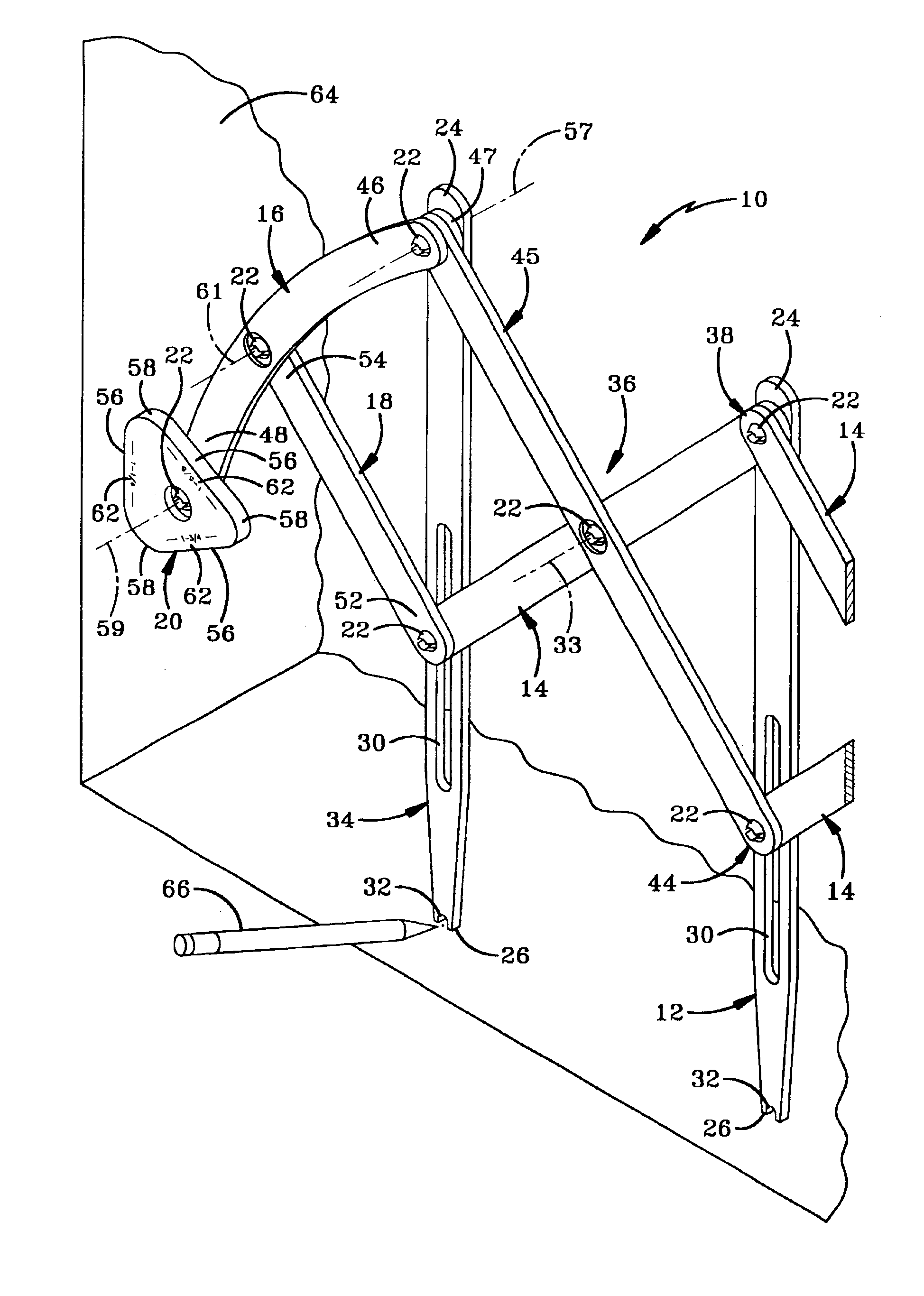
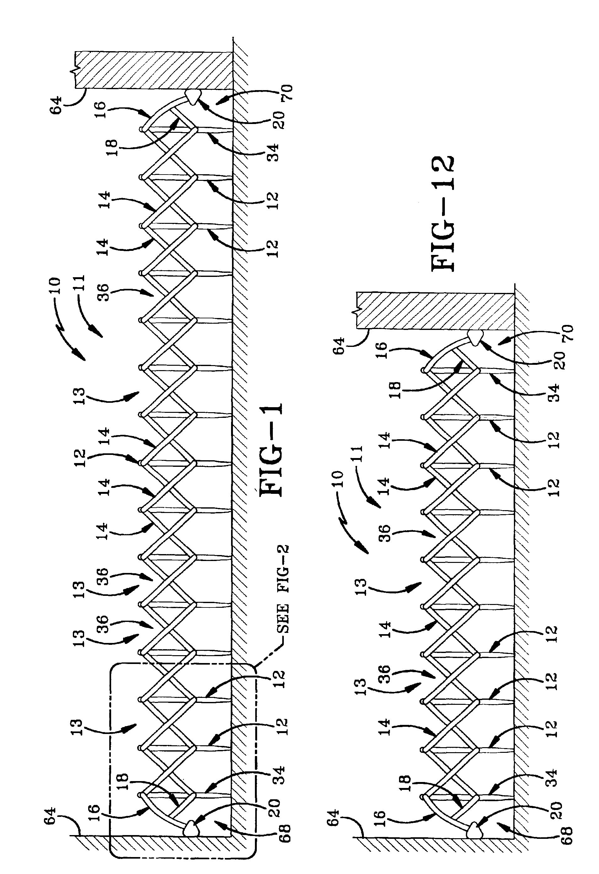
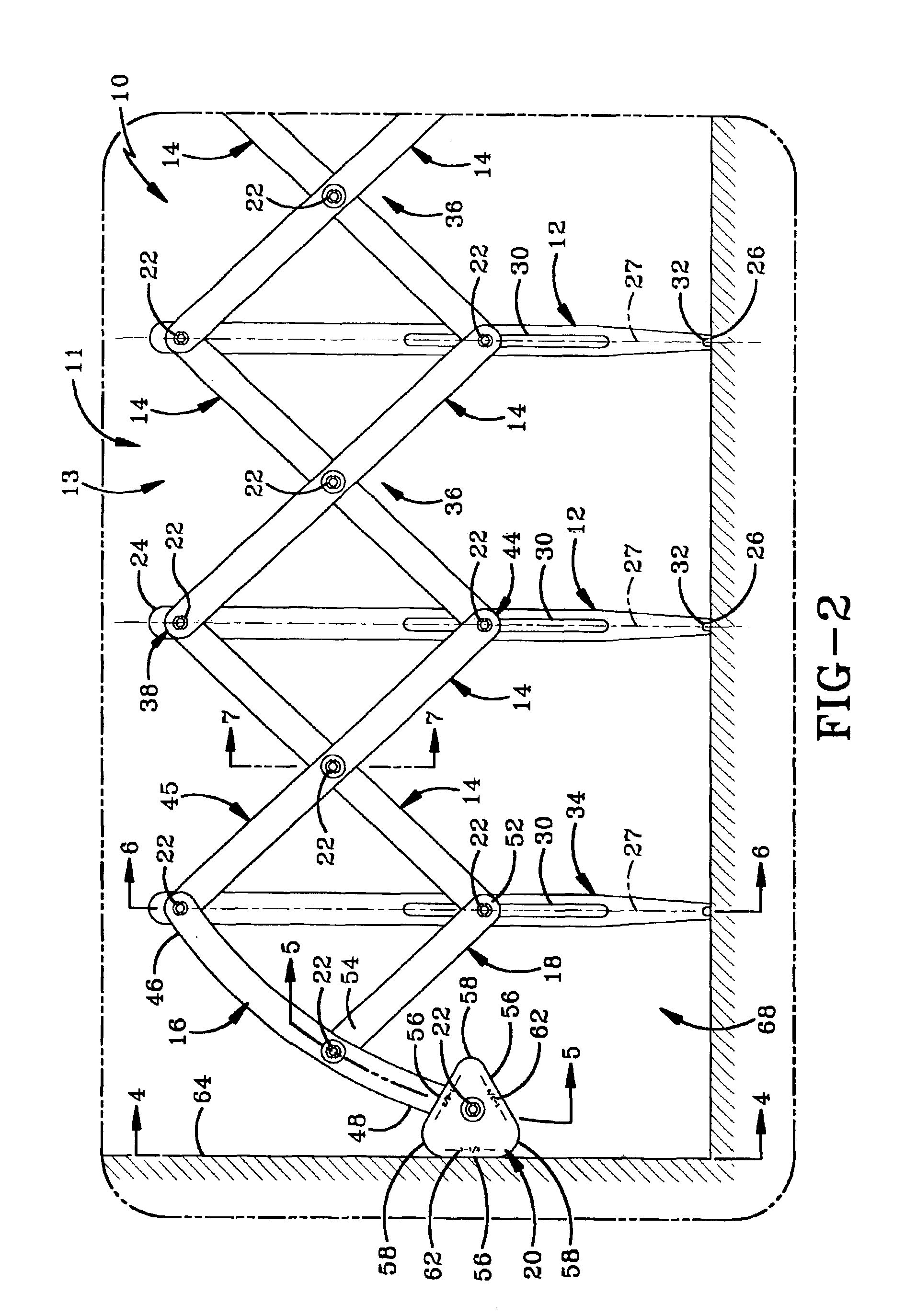
The spacer tool of the present invention is indicated generally by the numeral 10 in the drawings. Tool 10 generally includes a pantographic assembly 11 with an arm 16 extending from at least one end of assembly 11. Arm 16 is supported by a finger 18 that extends intermediate arm 16 and assembly 11. Assembly 11 includes at least one extendable and retractable pantograph unit 13. Each unit 13 includes two uprights 12 or 34 and two cross bars 14. A cam 20 may also be connected to arm 16. Fasteners, such as a plurality of push rivets 22 or bolts, removably connect these various parts to one another. Tool 10 has a first end 68 and a second end 70.

Tool 10 is used to lay out the spacing for balusters by placing the free end of arm 16 against a wall and extending assembly 11 to fit the desired length for the balusters. The user then marks the baluster location at the bottom of each upright. In accordance with the invention, arm 16 correctly spaces the first baluster from the wall.

The faste...


PUM


Abstract

An adjustable spacer tool for spacing balusters includes an extendable pantograpic assembly having a first and second end and including evenly-spaced parallel uprights and X-shaped sets of cross-bars pivotally connected to one another. Each X-shaped set is pivotally connected to a pair of uprights adjacent upper ends thereof and pivotally and slidably connected to the uprights adjacent lower ends thereof. An arm, finger and cam extend outwardly from each end of the assembly to provide spacing between each end of the assembly and a desired surface for various sets of same-width balusters. Each arm is pivotally connected to one end of the assembly and to one end of the finger. The other end of the finger is pivotally and slidably connected to a respective end of the assembly. Each cam is pivotally connected to the arm distal the assembly. Removable connections permit adjustment of the overall length of the tool and replacement of parts.

Description

BACKGROUND OF THE INVENTION1. Technical FieldThe invention relates generally to spacer tools used to measure the proper spacing between balusters in the installation thereof. More particularly, the invention relates to spacer tools with adjustable spacing capabilities. Specifically, the invention relates to an adjustable spacer tool that allows for adjustment of overall tool length and that allows for proper spacing between adjacent balusters and between a wall or other surface and a baluster which is to be installed adjacent the wall.2. Background InformationSpacer tools for measuring the distance between balusters, such as used in the installation of stairways for the support of handrails, are known in the art. However, several problems still exist. First, such spacers have set overall lengths and thus can only be used for that length, or alternately for longer distances by moving the spacer tool to overlap an area already measured. Since it is often desired to install balusters a...

Claims


Application Information

Patent Timeline
Patent Type & Authority Patents(United States)
IPC IPC(8): E04F21/26E04F21/00
CPCE04F21/26
Inventor BURRELL, TERRY D.MOORE, DANIEL L.
Owner L J SMITH INC
Learn More