Nacelle integration with reflexed wing for sonic boom reduction

a technology of reflexed wing and sonic boom, which is applied in the direction of airflow influencers, aircraft navigation control, transportation and packaging, etc., can solve the problems of supersonic flight over the united states and other countries, negative response and regulatory limitations on supersonic travel, and the difficulty of designing an aircraft with an n-wave signature of sufficiently low amplitude, so as to reduce the disturbance of sonic boom, enhance favorable interaction, and reduce drag

Active Publication Date: 2005-02-15
SUPERSONIC AEROSPACE INT
View PDF7 Cites 36 Cited by
  • Summary
  • Abstract
  • Description
  • Claims
  • Application Information

AI Technical Summary

Benefits of technology

This patent describes how an airplane's wings and engine are designed to reduce noise levels when flying at high speeds. By wrapping the engine's nacelle with a wing, researchers have created better interactions between these two parts which results in less resistance for the plane, allowing it to reach higher altitudes more easily while also reducing its overall sound level.

Problems solved by technology

This patent discusses how to make a commercially viable supersonic aircraft that reduces the loud sound produced by its sonic boom. The technical problem addressed is finding ways to modify the structure of the aircraft to slow down the formation of the sonic boom and ultimately achieve a quieter sonic boom that does not negatively impact performance or safety concerns.

Method used


Image

  • Nacelle integration with reflexed wing for sonic boom reduction
  • Nacelle integration with reflexed wing for sonic boom reduction
  • Nacelle integration with reflexed wing for sonic boom reduction

Examples


Embodiment Construction

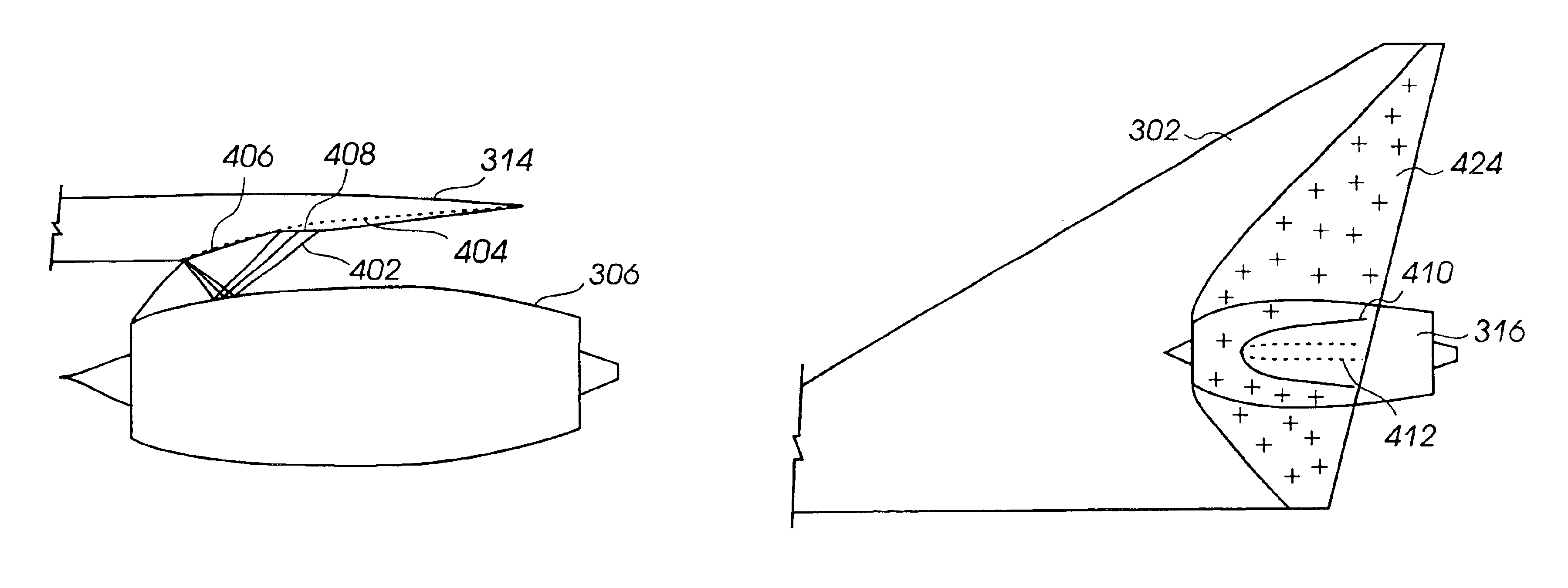
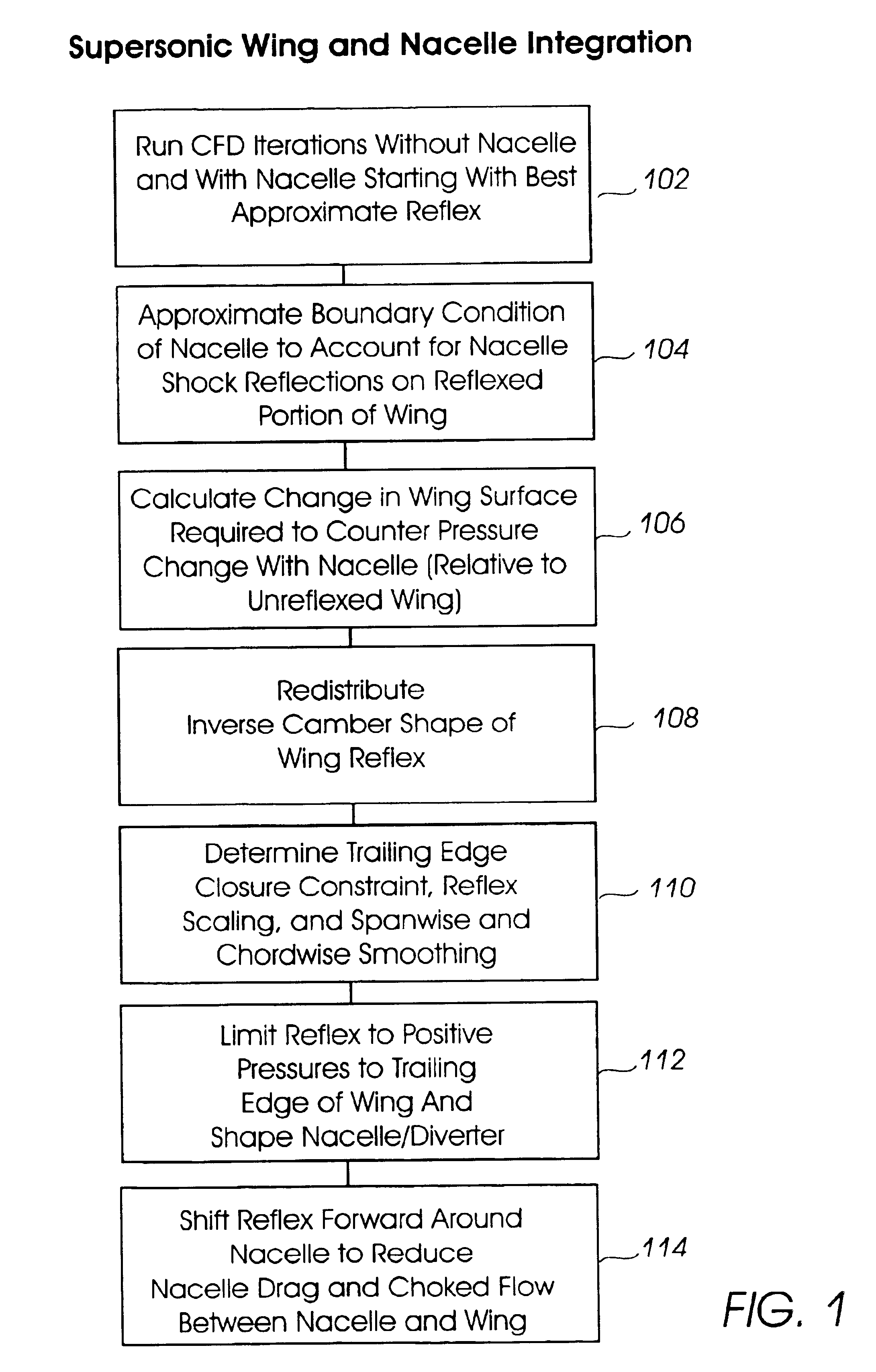
Referring to FIGS. 1, a flow diagram of an embodiment of a procedure for integrating a reflexed wing with an engine nacelle for a supersonic aircraft with reduced sonic boom capabilities is shown. Processes 102 through 114 can be utilized to determine the shape of a reflexed wing and a corresponding engine nacelle, as further described in the discussion of FIGS. 3A through 6F. Generally, at least some of processes 102 through 114 can be implemented as hardware and / or software logic instructions that are executable on a suitable computational system, such as one or more computer processors coupled to data input and output components.

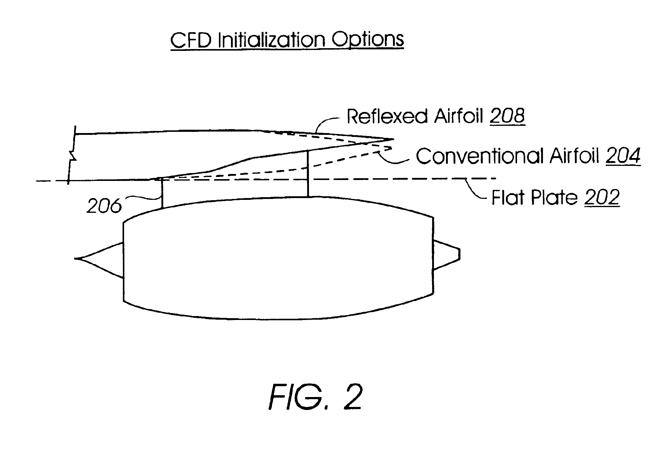
Various design constraints can be applied to parameters in processes 102 through 114. Process 102 typically includes performing computational fluid dynamics (CFD) iterations with and without an engine nacelle. In addition to performing CFD iterations with and without an engine nacelle, process 102 includes determining an initial reflex angle for an airfoi...


PUM


Abstract

A method for integrating an engine nacelle below the wing of a supersonic aircraft with low sonic boom capabilities includes determining the shape of a reflexed portion of the airfoil on the underside of the wing, and a corresponding shape for the upper surface of the nacelle to provide favorable interaction between the wing and the nacelle. In some configurations, the reflex and/or the nacelle are shaped to maintain positive pressure under the reflexed portion of the wing, to the trailing edge of the wing. A gull dihedral wing is designed to form a partial shroud around the nacelle. Such configurations reduce drag at the trailing edge of the wing, and the force of the positive pressure on the gull dihedral wing portion provides additional lift that partially offsets drag from the nacelle.

Description


Claims


Application Information

Patent Timeline
Owner SUPERSONIC AEROSPACE INT
Why Eureka
Try Eureka