Cable assembly retention

Inactive Publication Date: 2005-02-15
INTEL CORP
View PDF9 Cites 19 Cited by
  • Summary
  • Abstract
  • Description
  • Claims
  • Application Information

AI Technical Summary

Problems solved by technology

Further, such a tie wrap is removed generally by cutting the tie wrap from the materials, which destroys the tie wrap.
In some environments, cutting the tie wraps is undesirable.
Once the cable assembly has been removed, it may be difficult to ascertain its original location or configuration.

Method used


Image

  • Cable assembly retention
  • Cable assembly retention
  • Cable assembly retention

Examples


Embodiment Construction

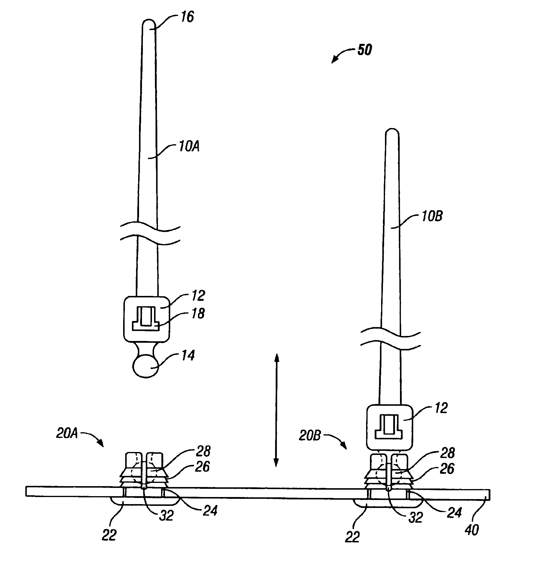
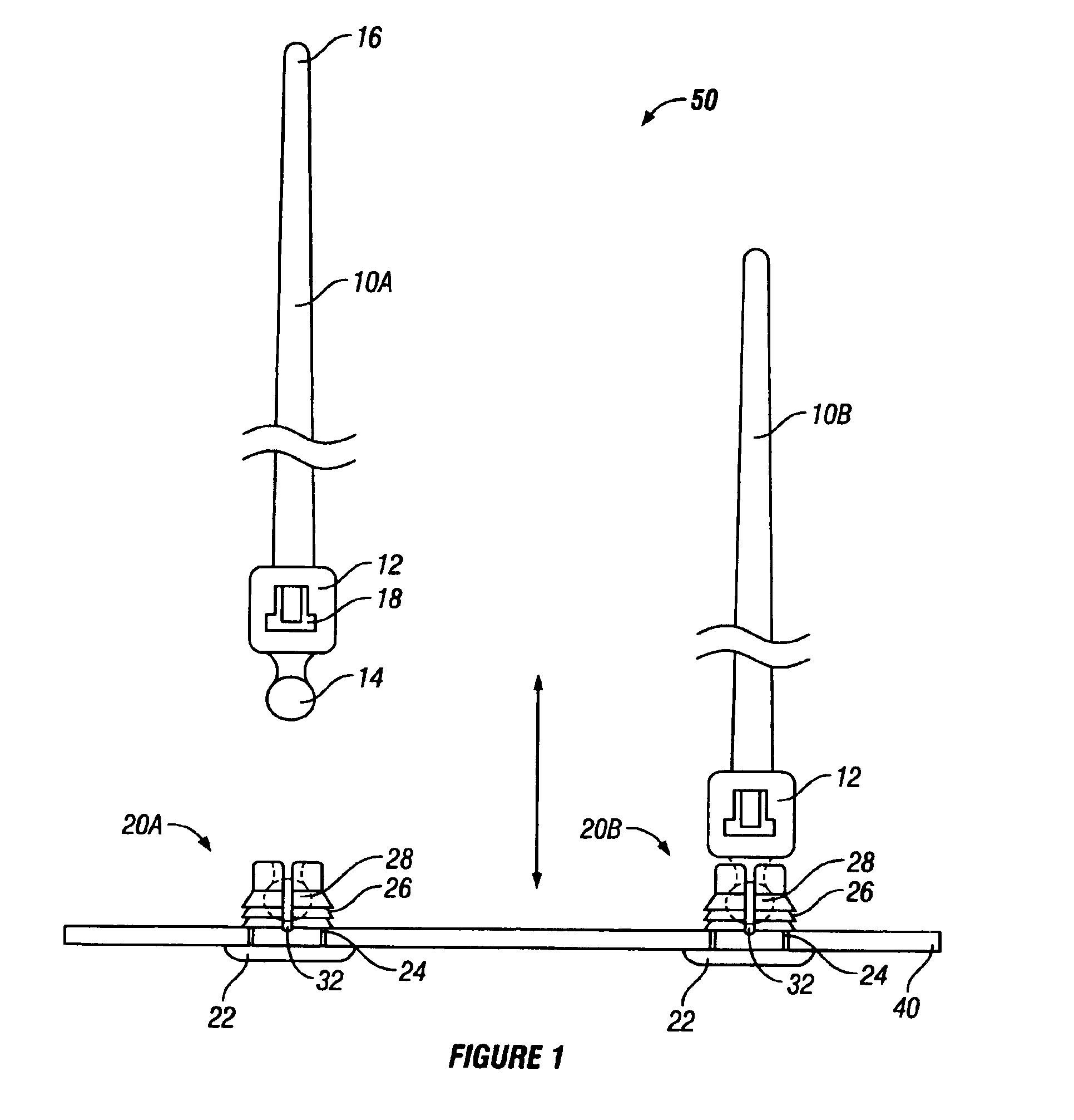
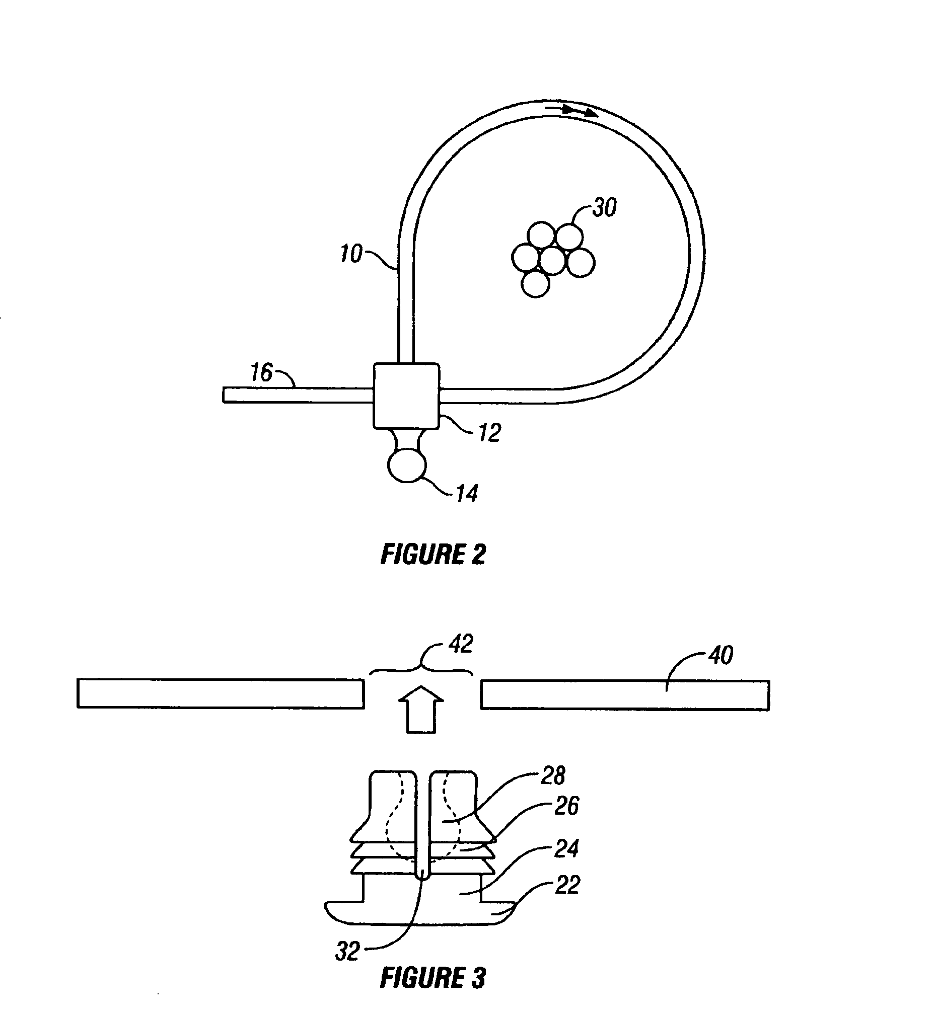
According to the embodiments described herein, a tie wrap assembly is disclosed, for retaining a cable assembly against a chassis. The tie wrap assembly comprises a tie wrap, for retaining the cable assembly, and a tie wrap base, for connection to the chassis. The tie wrap includes a shaped engagement member for fittably coupling to an orifice within the tie wrap base. The tie wrap base is flexible, allowing the engagement member to be repeatedly inserted into and removed from the tie wrap base, as well as being fit through a hole in the chassis. One or more tie wrap bases are disposed at pre-arranged locations along the chassis. The tie wrap assembly allows cabling to be consistently routed along the pre-arranged locations, facilitating the consistent placement of cables in mass-produced systems, and allowing the removal and installation in the pre-arranged locations.

In the following detailed description, reference is made to the accompanying drawings, which show by way of illustra...


PUM


Abstract

A tie wrap assembly comprises a tie wrap, for retaining a cable assembly, and a tie wrap base, for connecting the cable assembly to the chassis. The tie wrap includes a shaped engagement member for fittably coupling to an orifice within the tie wrap base. The tie wrap base is flexible, allowing the engagement member to be repeatedly inserted into and removed from the tie wrap base, as well as being fit through a hole in the chassis. One or more tie wrap bases are disposed at pre-arranged locations along the chassis. The tie wrap assembly allows cabling to be consistently routed along the pre-arranged locations, facilitating the consistent placement of cables in a mass production environment.

Description

FIELD OF THE INVENTIONThis invention relates to tie wraps and, more particularly, to a reusable tie wrap retention solution.BACKGROUND OF THE INVENTIONTie wraps are strips of material used to retain or collect a length of cable, wires, or other materials. Tie wraps may be used to gather a group of wires emanating from a computer system or to gather ribbon cable within the computer system chassis, for example. Where the materials to be contained are long, multiple tie wraps may be disposed at intervals along the materials.Tie wraps are available in many forms. Generally made from an elastomeric material such as nylon, the tie wrap generally includes a clasp at one end through which the other end passes, forming a loop. The tie wrap is placed transverse to the materials to be contained, the end is fed through the clasp, and the end is pulled, tightening the tie wrap around the materials. Sometimes, the clasp includes teeth which allow one-way engagement of the tie wrap. Once the tie w...

Claims


Application Information

Patent Timeline
IPC IPC(8): H02G3/32H02G3/30
CPCH02G3/32Y10T24/1498
Inventor HARRISON, JOE A.VALPIANI, ANTHONY P.
Owner INTEL CORP
Why Eureka
Try Eureka