
Biaxial flow inflator with independently adjusted gas orifices

a gas orifice and biaxial flow technology, applied in the direction of pedestrian/occupant safety arrangement, vehicle components, vehicular safety arrangments, etc., can solve the problems of further design problems, insufficient inflation gas pressure at the outermost extent of the inflatable curtain, and difficulty in achieving rapid inflation with known inflator designs, etc., to achieve the effect of reducing manufacturing and installation costs, ensuring safety and comfort, and ensuring inflation

Inactive Publication Date: 2005-02-15
AUTOLIV ASP INC
View PDF42 Cites 10 Cited by
  • Summary
  • Abstract
  • Description
  • Claims
  • Application Information

AI Technical Summary

Benefits of technology

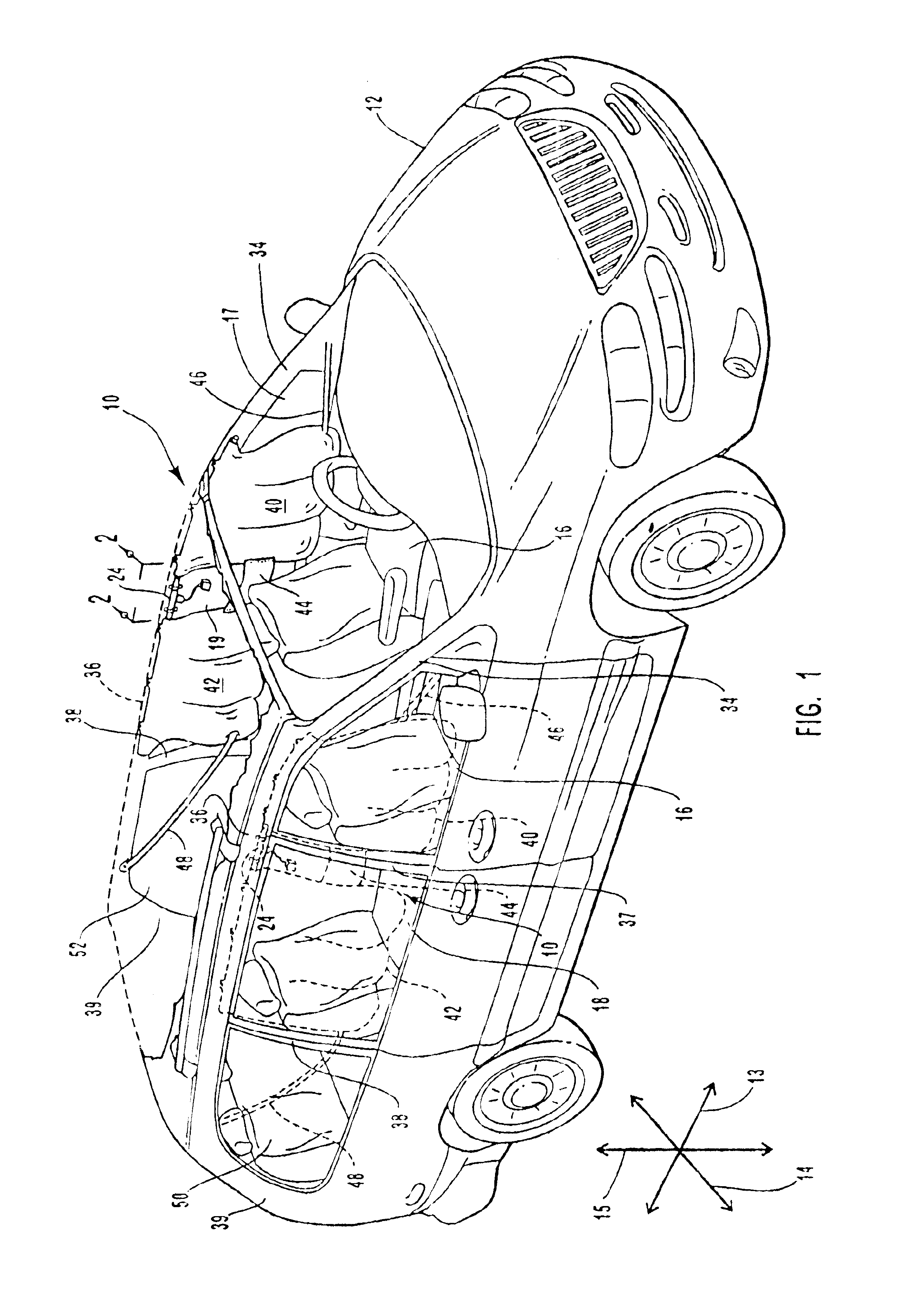
The apparatus of the present invention has been developed in response to the present state of the art, and in particular, in response to the problems and needs in the art that have not yet been fully solved by currently available inflators. Thus, it is an overall objective of the present invention to provide an inflator and related systems and methods that provide rapid, even inflation with a minimum of manufacturing and installation cost.
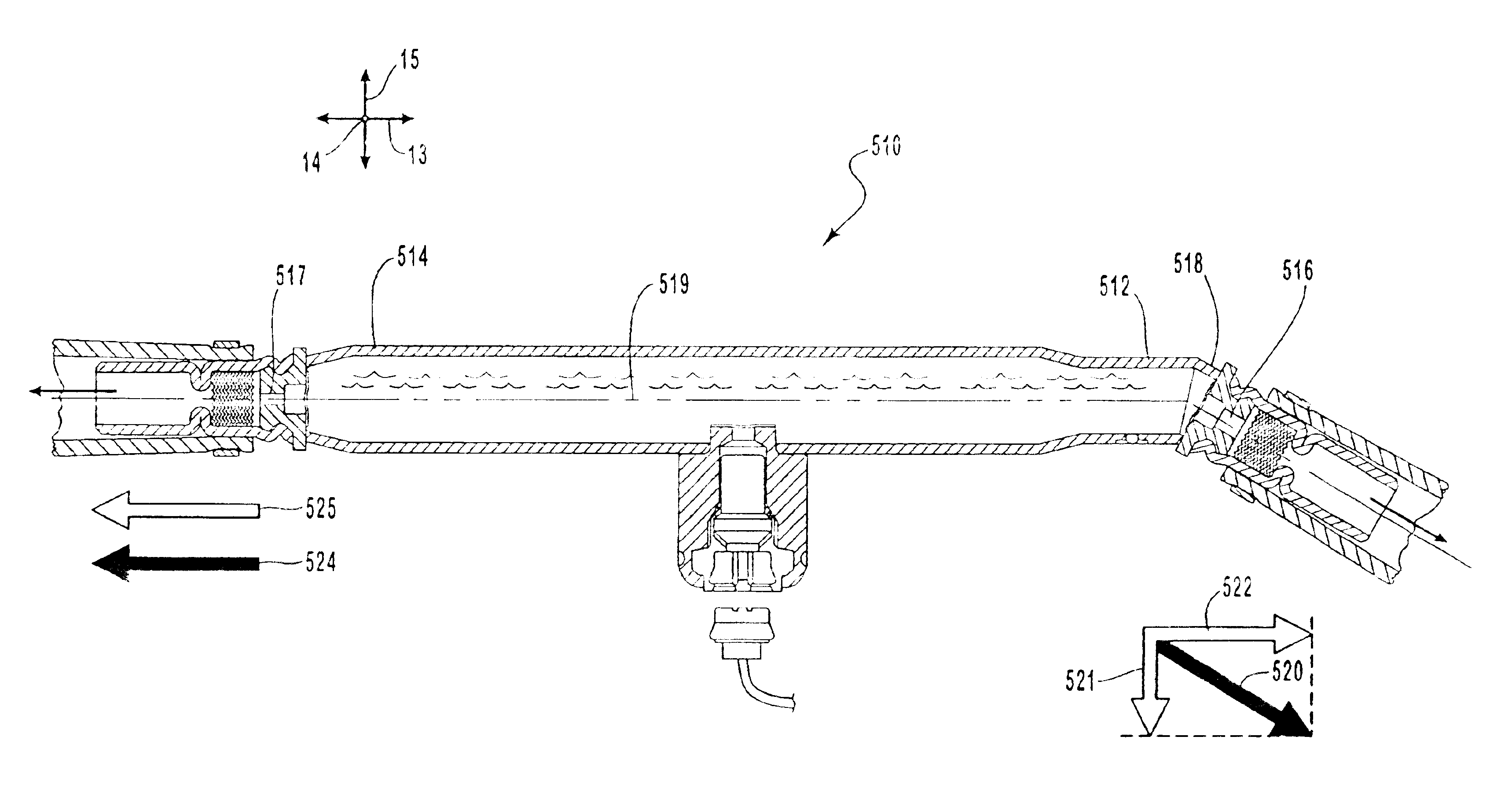
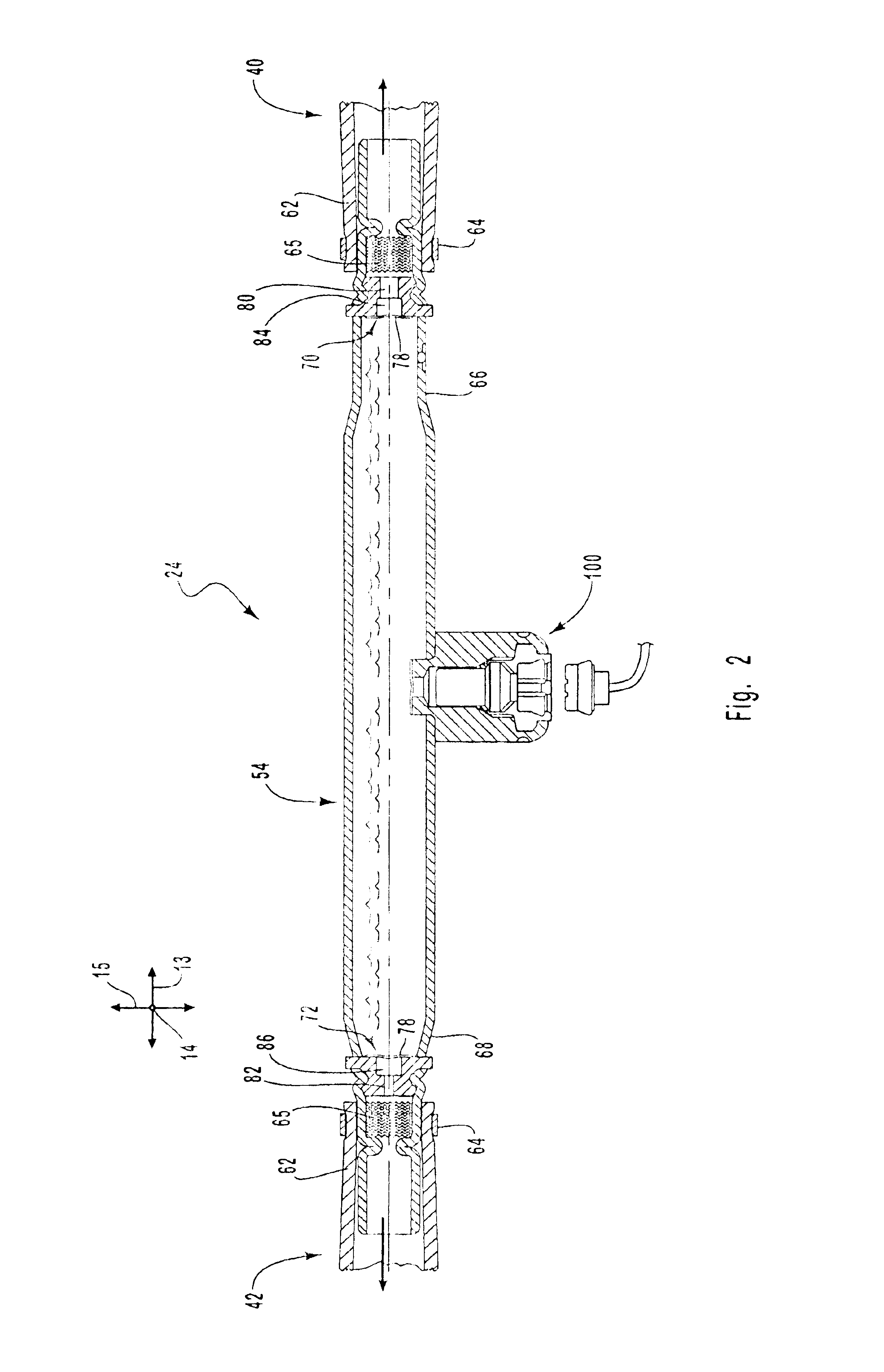
The gas chamber may also have a first retention orifice and a second retention orifice. The first and second retention orifices are configured to have an open state and a closed state. The closed state may be accomplished by placing burst disks or other sealing mechanisms in front of each of the retention orifices. The open state occurs when the burst disks are forced through the retention orifices to allow gas to exit the inflator. The retention orifices may also function similarly to the ejection orifices by controlling the mass flow rate of gas exiting the inflator. The effective cross-sectional area of each of the retention orifices can be adjusted such that the two retention orifices eject gas at different mass flow rates.
The use of two different gas flows having different mass flow rates from a single inflator allows for a large degree of control in deploying inflatable curtains. The different gas flows can be established to inflate two different sized volumes, such as two different sized sections in an inflatable curtain. The gas flow with the larger mass flow rate could inflate a larger volume and a smaller gas flow with a smaller mass flow rate could inflate a smaller volume. Alternatively, the two different gas flows can be employed to inflate two substantially different volumes at different times or at different pressures.

Problems solved by technology

Thus, the outermost extents of the inflatable curtain may receive insufficient inflation gas pressure to inflate to the optimal protective pressure.
Even with somewhat shorter inflatable curtains, even and rapid inflation can be difficult to achieve with known inflator designs.
The problem of uneven gas distribution creates further design problems in the advanced and intelligent air bag deployment systems.
Unfortunately, this presents the problem of simultaneously inflating two or more differently sized inflatable curtains at a single instant.
However, each inflator adds significant cost to the overall price of the automobile, causing some automobile manufacturers to decide against multiple side impact inflatable curtains.
While current innovations are addressing the problem of simultaneously inflating two similarly sized inflatable curtains, no technology is presently commercially available to inflate two differently sized inflatable curtains with a single inflator.
Thus, present inflatable curtain systems are not capable of providing the controllability that may be obtained from an inflator having two independently controlled flows of gas.

Method used


Image

  • Biaxial flow inflator with independently adjusted gas orifices
  • Biaxial flow inflator with independently adjusted gas orifices
  • Biaxial flow inflator with independently adjusted gas orifices

Examples


Embodiment Construction

The presently preferred embodiments of the present invention will be best understood by reference to the drawings, wherein like parts are designated by like numerals throughout. It will be readily understood that the components of the present invention, as generally described and illustrated in the figures herein, could be arranged and designed in a wide variety of different configurations. Thus, the following more detailed description of the embodiments of the apparatus, system, and method of the present invention, as represented in FIGS. 1 through 10, is not intended to limit the scope of the invention, as claimed, but is merely representative of presently preferred embodiments of the invention.

The present invention provides an apparatus and method whereby problems associated with previously known inflators can be resolved. More specifically, through the use of independently adjustable orifices, a single inflator can be produced to provide varying streams of gas to two separate in...


PUM


Abstract

An airbag or inflatable curtain inflator for producing two differing gas flows is disposed. The inflator has a gas chamber, a first orifice, and a second orifice. The first orifice has a different effective cross-sectional area than the second orifice. The two different cross-sectional areas allow the first orifice to produce a mass flow rate of gas that is different from the second orifice. The mass flow rates of gas may be related to the volume of an inflatable curtain into which the gas is ejected. Thus, two differently sized volumes of an inflatable curtain may be simultaneously inflated with a single inflator.

Description

BACKGROUND OF THE INVENTION1. Field of the InventionThe present invention relates to a dual flow inflator for injecting multiple gas flows of gas into an automobile airbag system. More specifically, the present invention relates to a dual flow injector structured to provide independently adjusted gas flows to selected portions of an inflatable airbag system, such as an inflatable curtain.2. Description of Related ArtThe inclusion of inflatable safety restraint devices, or airbags, is now a legal requirement for many new vehicles. Airbags are typically installed in the steering wheel and in the dashboard on the passenger side of a car. In the event of an accident, an accelerometer within the vehicle measures the abnormal deceleration and triggers the expulsion of rapidly expanding gases from an inflator. The expanding gases fill the airbags, which immediately inflate in front of the driver and passenger to protect them from impact against the windshield. Side impact airbags, known as...

Claims


Application Information

Patent Timeline
IPC IPC(8): B60R21/26B60R21/16B60R21/264B60R21/268
CPCB60R21/26B60R21/232B60R2021/2685B60R2021/2633B60R2021/2612
Inventor DINSDALE, PAULGREEN, DAVID J.RINK, KARL K.
Owner AUTOLIV ASP INC
Learn More