Devices for cavitational mixing and pumping and methods of using same

a technology of cavitational mixing and pumping, which is applied in the direction of mixing, transportation and packaging, rotary stirring mixers, etc., can solve the problems of ineffective hydrodynamic cavitation method of sonochemical reactions, inability to achieve large-scale volumes, and inability to achieve sonochemical reactions

Inactive Publication Date: 2005-02-22
ARISDYNE STSTEMS INC
View PDF35 Cites 116 Cited by
  • Summary
  • Abstract
  • Description
  • Claims
  • Application Information

AI Technical Summary

Benefits of technology

The present invention provides a method for mixing and pumping liquids using an agitator head assembly. The assembly creates cavitation in the liquid to cause mixing, and the centrifugal forces created by rotating the assembly push the mixed liquid out of the housing. The technical effect is a more efficient and effective method for mixing and pumping liquids.

Problems solved by technology

The technical problem addressed in this patent is how to effectively apply sonochemical methods to larger scales of liquid-based materials without losing their effectiveness or requiring excessive amounts of energy.

Method used


Image

  • Devices for cavitational mixing and pumping and methods of using same
  • Devices for cavitational mixing and pumping and methods of using same
  • Devices for cavitational mixing and pumping and methods of using same

Examples


Embodiment Construction

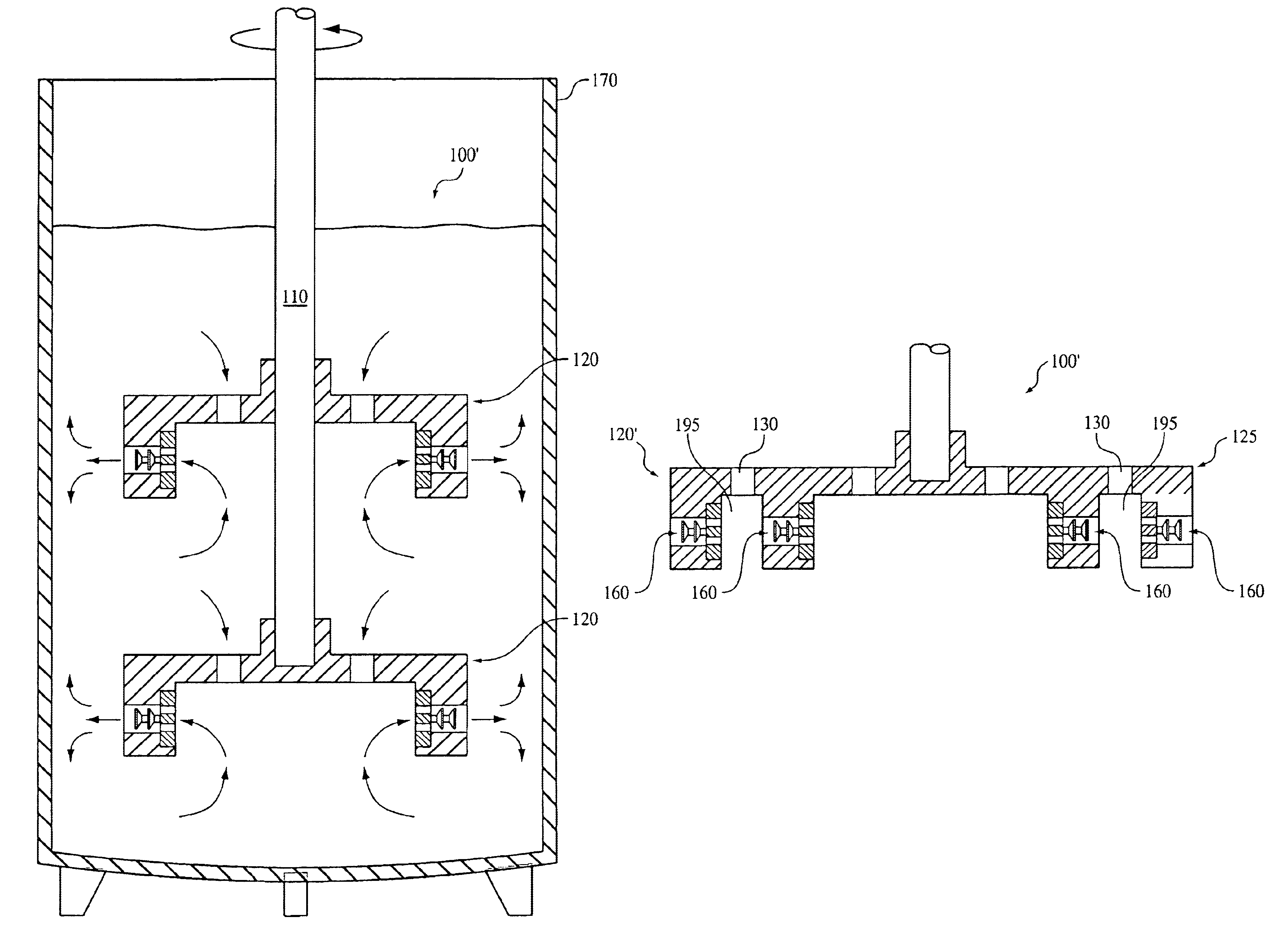
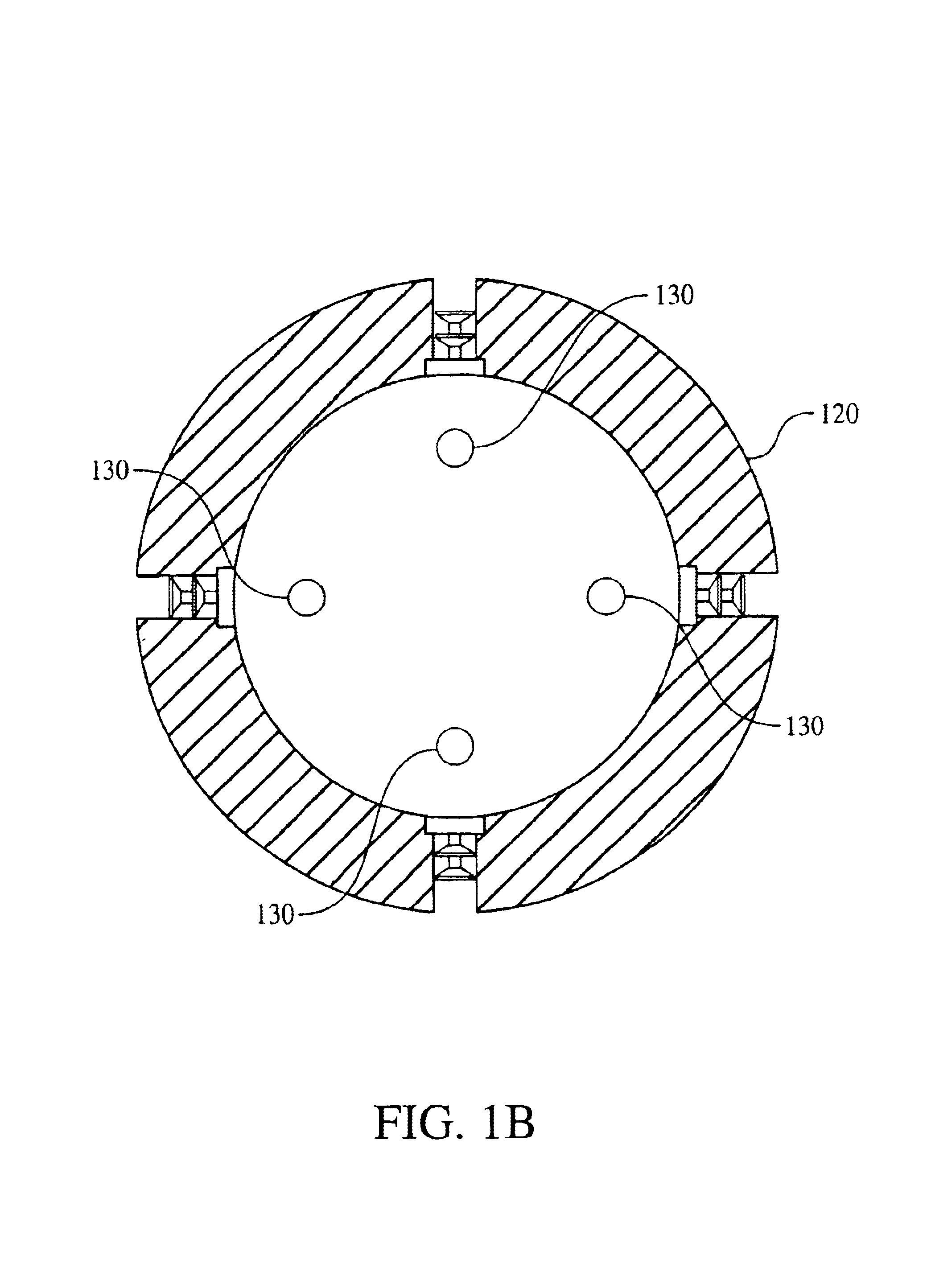
Referring to FIG. 1A, a mixing device 100 according to the present invention includes a shaft 110, an agitator head assembly 120, also known as a rotor or mixer and means for rotating the shaft (not shown). Preferably, agitator head assembly 120 is pressure fitted and fixed to the lower portion of the shaft 110. Although the preferred embodiment utilizes a pressure fitted technique of connecting the agitator head assembly 120 to the shaft 110, it is contemplated that additional connecting techniques could be used to fix the agitator head assembly 120 to the shaft 110. In other embodiments, the agitator head assembly 120 is pinned, glued, welded, threaded, bolted, riveted or the like to the shaft 110. The upper portion of the shaft 110 is connected to a motor (not shown) which when operated, rotates the shaft 110. It is understood that other means of rotating the shaft 110 may be implemented including, but not limited to, pulleys, cranks or the like.

Continued reference to FIG. 1A ill...


PUM

PropertyMeasurementUnit
Volumeaaaaaaaaaa
Shapeaaaaaaaaaa
Cavitation enthalpyaaaaaaaaaa

Abstract

The present invention provides for a cavitational mixing and/or pumping device and method including a body having a base portion and a peripheral wall extending from the base portion and defining an inlet space therebetween. Additionally, the base portion includes at least one inlet port disposed therein that is in fluid communication with the inlet space. The peripheral wall includes an outlet channel disposed therein that is in fluid communication with the inlet space. A cavitation assembly is disposed within the outlet channel. Alternatively, a plurality of cavitation assemblies may be disposed within the outlet channel.

Description


Claims


Application Information

Patent Timeline
Owner ARISDYNE STSTEMS INC
Why Eureka
Try Eureka