
High frequency coaxial connector

Inactive Publication Date: 2005-02-22
SV MICROWAVE
View PDF10 Cites 6 Cited by
  • Summary
  • Abstract
  • Description
  • Claims
  • Application Information

AI Technical Summary

Benefits of technology

The bayonet sleeve overlies the main body to such an extent that angling of the bayonet sleeve with respect to the main body is substantially prevented. That is, the bayonet sleeve cannot be angled substantially with respect to the main body owing to the bayonet sleeve overlying the main body

Problems solved by technology

Many design engineers consider them as an after thought, yet without a properly designed connector many of today's systems would not have been realized. nor would they have worked.
Initially, there were minimal performance parameters associated with these devices.
However, in modem higher frequency applications, the conventional BNC connector is inadequate.
The conventional BNC connector suffers from poor stability between the bayonet sleeve and the main body.
However, as the frequency increases, the signal degrades; signal reflections may occur, clock signals may be ramped,

Method used


Image

  • High frequency coaxial connector
  • High frequency coaxial connector
  • High frequency coaxial connector

Examples


Example

DETAILED DESCRIPTION OF THE PREFERRED EMBODIMENTS AND DRAWINGS

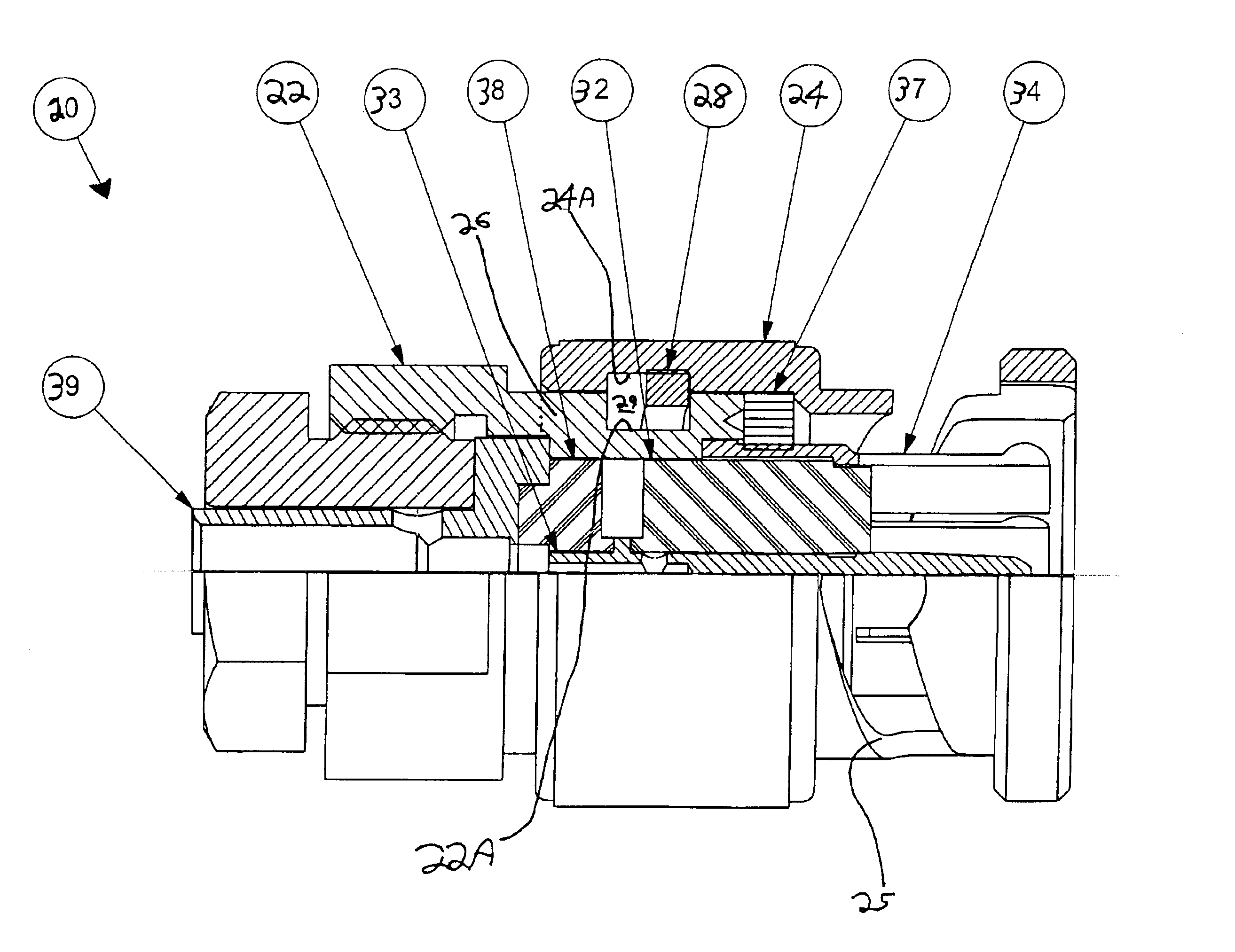
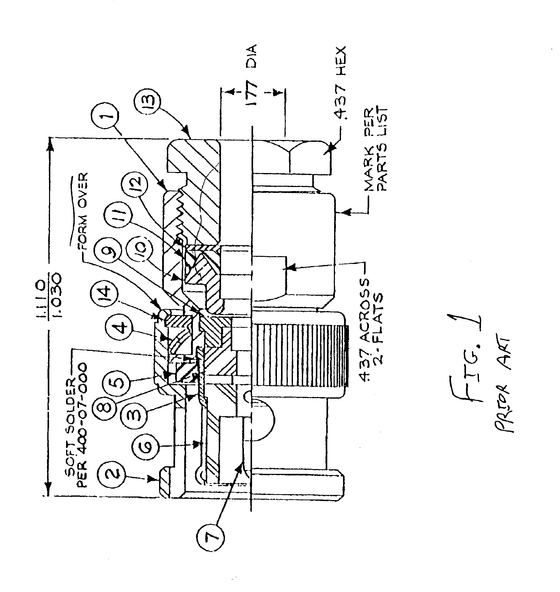
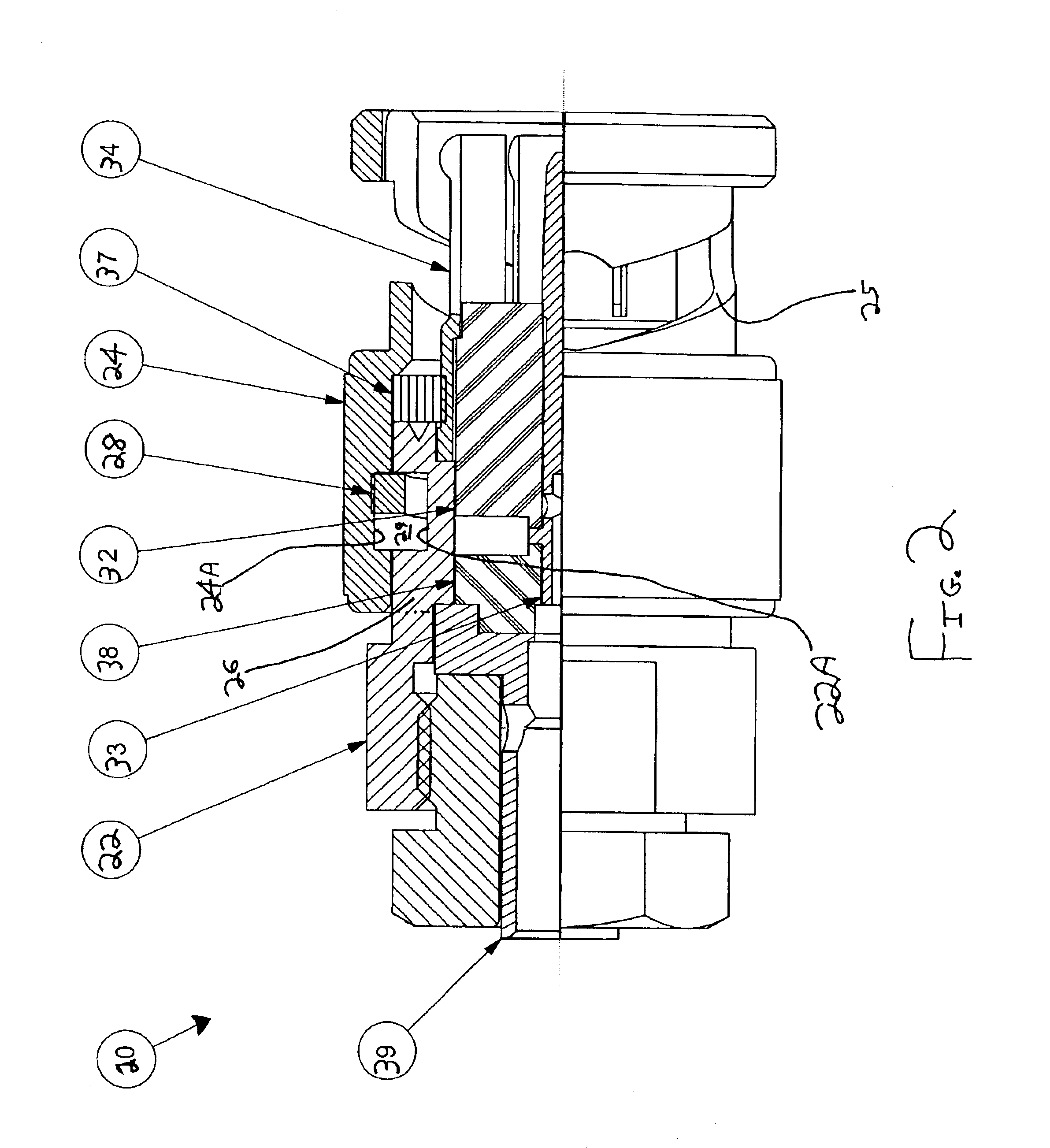
Description of the invention will now be given with reference to the attached FIGS. 2-4. It should be noted that these drawings are exemplary in nature and in no way serve to limit the scope of the invention, which is defined by the claims appearing hereinbelow.

The preferred embodiment of the inventive connector is shown in partial section in FIGS. 2 and 3 as connector 20. A main body 22 is provided, for example, to receive the end of a coaxial cable or other transmission media, and a bayonet sleeve 24 is disposed at least partially overlying the main body 22. Bayonet sleeve 24 overlies rear section 26 of main body 22 to such an extent that the bayonet sleeve cannot be cocked or angled to any significant degree with respect to main body 22. In the preferred embodiment, rear section 26 is at least 25% of the overall length of the bayonet sleeve, more preferably at least 33%.

An outer annular groove 22A is formed on main bod...


PUM


Abstract

A coaxial connector suitable for high frequency applications is provided. The main body of the connector has an annular groove. A bayonet sleeve is provided at least partially slidably overlying the main body and having a recess groove at least partially corresponding to the annular groove in the main body. A biasing mechanism biases against the main body and the bayonet sleeve and is preferably disposed in the annular and recess grooves. The biasing mechanism exerts biasing force in a longitudinal direction of the connector to maintain the relative longitudinal position of the bayonet sleeve with respect to the main body. Because of the overlap of the bayonet sleeve and the main body acting in conjunction with the biasing mechanism, the bayonet sleeve is maintained in a stable, straight configuration, and signal loss or degradation is minimized.

Description

BACKGROUND OF THE INVENTION1. Field of the InventionThe invention relates to connectors, and more specifically to “RF” coaxial connectors for high frequency systems.2. Description of the Related ArtRF connectors are the forgotten component of microwave systems even though they have been in use for 100 years or so. Many design engineers consider them as an after thought, yet without a properly designed connector many of today's systems would not have been realized. nor would they have worked.Initially, there were minimal performance parameters associated with these devices. During WWII, the emerging radar technology gave rise to the need for frequency-dependent performance parameters. During this time, Paul Neill, an engineer at Bell Labs, is credited with developing the first performance driven connector, the type “N”. (The type N is a threaded air dielectric interface connector which is still used today.) Shortly after the development of the N connector, Karl Concelman, an engineer...

Claims


Application Information

Patent Timeline
IPC IPC(8): H01R13/00H01R13/625H01R13/646
CPCH01R13/625H01R24/40H01R2103/00
Inventor MORELLI, JOHN
Owner SV MICROWAVE
Learn More