Smoke alarm and mounting kit

a smoke alarm and mounting kit technology, applied in the field of mounting smoke alarms, can solve the problems of limited utility in allowing the mounting of smoke alarms

Inactive Publication Date: 2005-02-22
SAFETY WISE
View PDF22 Cites 30 Cited by
  • Summary
  • Abstract
  • Description
  • Claims
  • Application Information

AI Technical Summary

Problems solved by technology

While these devices fulfill their respective objectives and requirements, the aforementioned patents have limited utility in allowing for smoke alarms to be mounted to support surfaces which are difficult to reach, particularly where the smoke alarms must be accessed from time to time for servicing, as to replace a battery, or for regular cleaning per all smoke detector manufacturer instructions, or to replace defective units, or upgrade an entire system by replacing all units.

Method used


Image

  • Smoke alarm and mounting kit
  • Smoke alarm and mounting kit
  • Smoke alarm and mounting kit

Examples


second embodiment

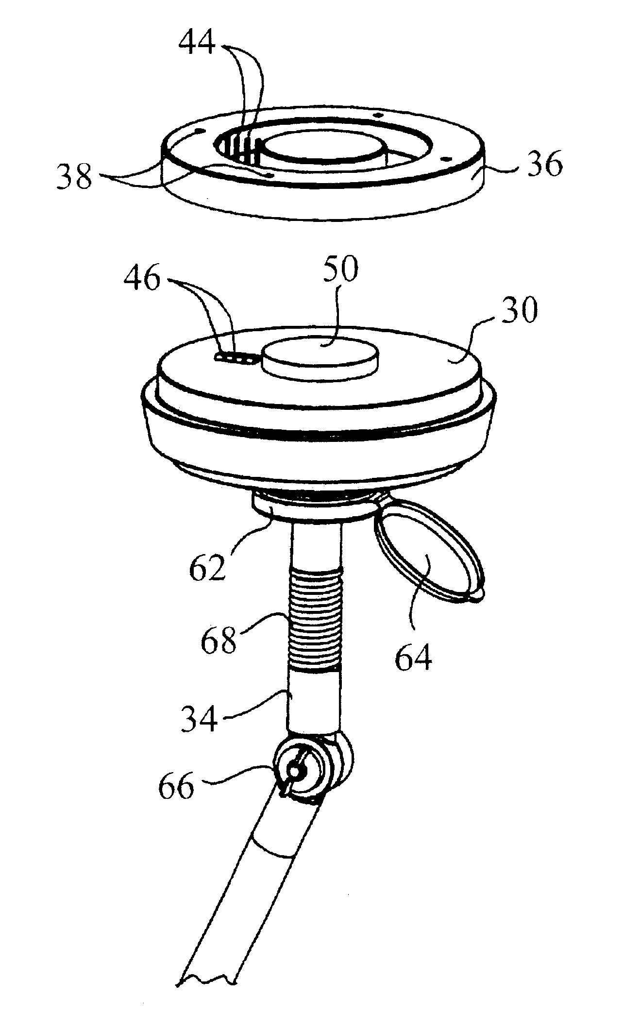
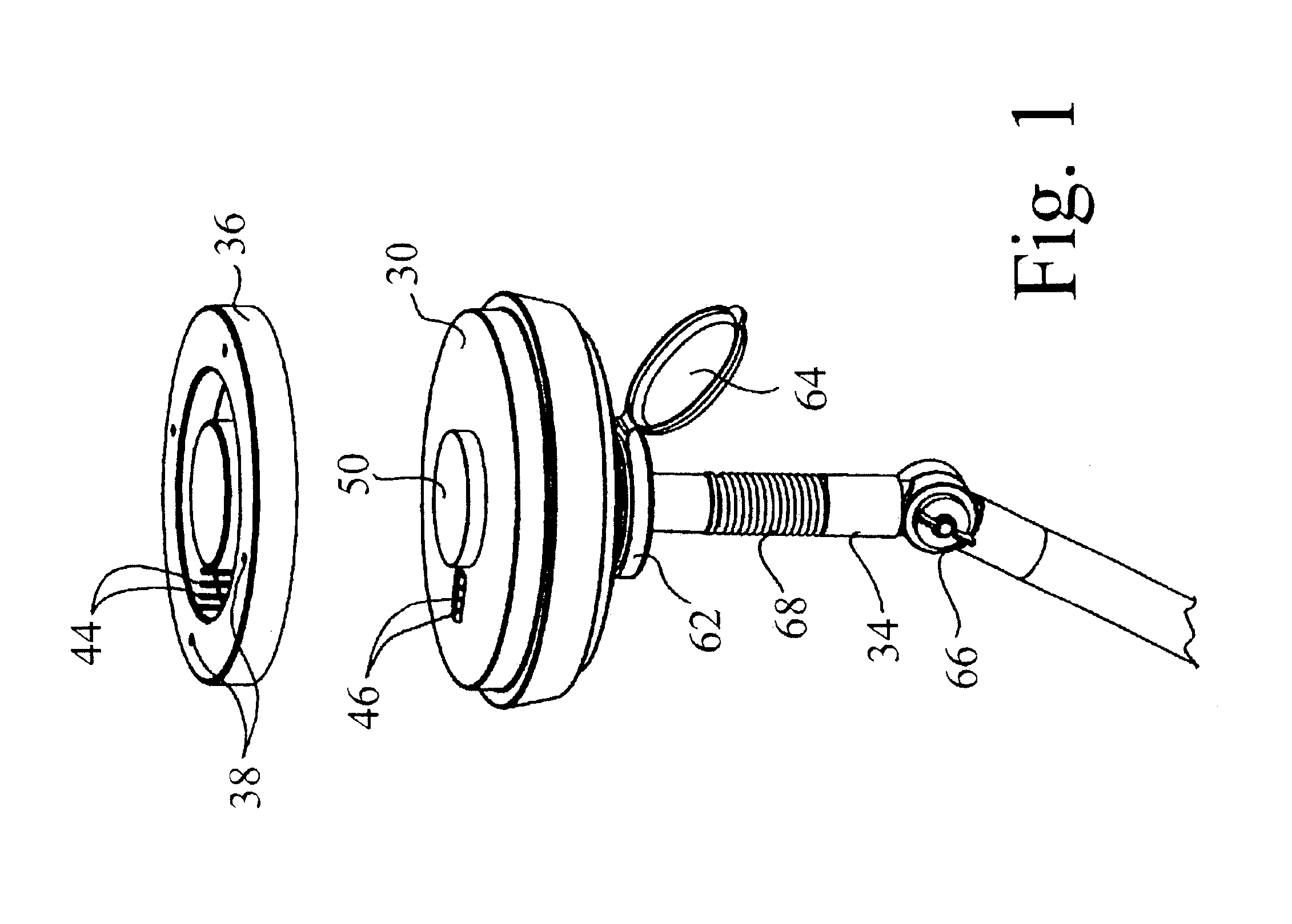
0031]FIG. 7 is an exploded view of the present invention;

[0032]FIG. 8 is an enlarged, exploded partial view of the lower connection of a smoke detector and pole according to the second embodiment of the present invention;

[0033]FIG. 9 is an exploded perspective view of the lower screw plate and lower nut plate of the second embodiment of the present invention;

[0034]FIG. 10 is a side view of the second embodiment of the present invention;

[0035]FIG. 11 is a cross-sectional view taken along line 11—11 of FIG. 10;

third embodiment

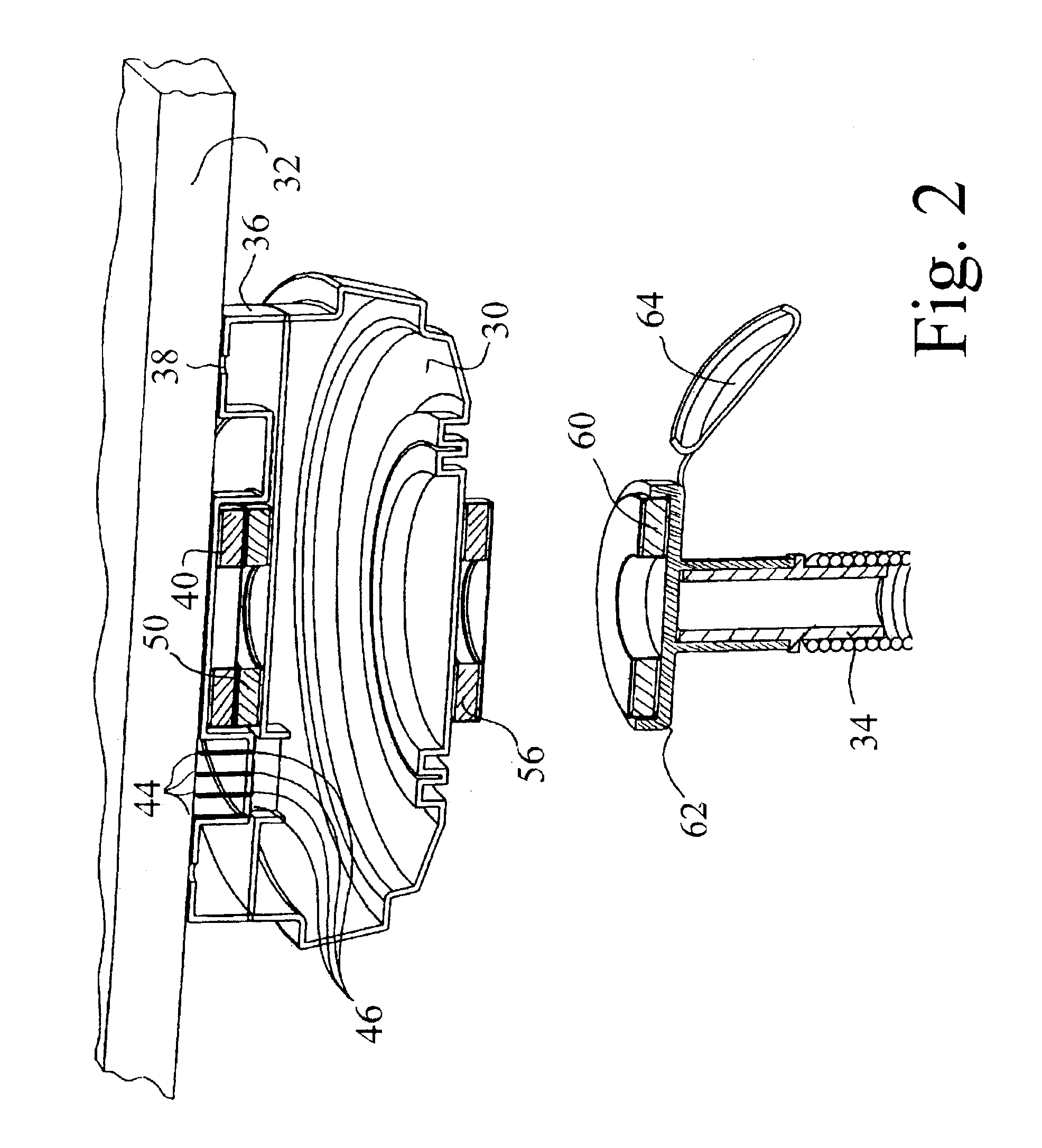
[0036]FIG. 12 is a side, partial cross-sectional view of the present invention;

[0037]FIG. 13 is an exploded view of the third embodiment of the present invention; and

[0038]FIG. 14 is an enlarged perspective view of the pole attachment structure of the third embodiment of the present invention.


PUM


Abstract

A mounting kit and smoke detecting apparatus releasably mountable to a distant support surface, including a smoke detector weighing W, a support plate securable to the support surface and releasably securable to the smoke detector by a separating force of Y, and a longitudinal member having a proximate end graspable by a user and a distal end releasably securable to the smoke detector. A selectable first connector on the distal end is releasably securable to the smoke detector for mounting the smoke detector to the support plate and a selectable second connector is securable to the smoke detector for detaching the smoke detector from the support plate. The first connector is secured to the smoke detector by a separating force no greater than X and the second connector is secured to the smoke detector by a separating force no less than Z. At least one of X<(Y−W) and X<Y is true, and at least one of Y<Z and (Y−W)<Z is true.

Description

[0002]This application claims the benefit of U.S. Provisional Appl. No. 60 / 371,780, filed Apr. 11, 2002 by Laura Lynn McGreal and Timothy Richard McGreal entitled “Smoke Alarm Mounting / Installation / Removal From a Distance System and Method”.BACKGROUND OF THE INVENTION[0003]The present invention is directed toward securing devices and more particularly toward mounting smoke alarms to support surfaces which are difficult to reach.[0004]The use of various structures to secure devices at desired locations is, of course, well known in the prior art. Known prior art securing devices include, for example, U.S. Pat. No. 5,149,038; U.S. Pat. No. 4,702,452; U.S. Pat. No. 5,186,653; U.S. Pat. No. 5,188,332; U.S. Pat. No. 5,153,567; U.S. Pat. No. 5,563,766, U.S. Pat. No. 5,577,696 and U.S. Pat. No. Design 246,635.[0005]While these devices fulfill their respective objectives and requirements, the aforementioned patents have limited utility in allowing for smoke alarms to be mounted to support su...

Claims


Application Information

Patent Timeline
Patent Type & Authority Patents(United States)
IPC IPC(8): G08B29/00G08B29/14G08B17/10
CPCG08B17/10G08B29/145Y10T16/44G08B17/113
Inventor MCGREAL, TIMOTHY R.MCGREAL, LAURA L.MCGREAL, MARILYN L.
Owner SAFETY WISE
Why Eureka
Try Eureka