Particle monitors and method(s) therefor

a particle monitor and particle technology, applied in the direction of fire alarms, liquid/fluent solid measurement, fluid speed measurement using thermal variables, etc., can solve the problem of reducing the detection accuracy of detectors, and producing a large number of very small solid particles

Inactive Publication Date: 2007-02-01
SIEMENS SWITZERLAND
View PDF30 Cites 49 Cited by
  • Summary
  • Abstract
  • Description
  • Claims
  • Application Information

AI Technical Summary

Benefits of technology

[0026] In yet another aspect of the invention, there is provided a particle monitor chamber, comprising a first lens operable in association with a source of illumination, a second lens adapted to focus impinging light toward a receiver cell, and a primary iris configured to substantially prevent light emanating directly from the first lens to impinge on the second lens.
[0027] In a further aspect of the invention, there is provided a method of and device for determining the velocity of flu

Problems solved by technology

Fast flaming fires tend to produce a very large number of very small solid particles which may agglomerate into random shapes to form soot.
These detectors have relatively low sensitivity and have difficulty in detecting the presence of unwanted pyrolysis where large volumes of air pass through the area being monitored, thus diluting the ability for the detector to sense the presence of unwanted pyrolysis.
These detectors, however, are not considered to be true nephelometers as they are prone to being overly sensitive to a particular particle size range at the expense of other size ranges.
The disadvantage suffered by the above detectors is their relative insensitivity to very small particles characteristic of early pyrolysis and incipient fires, as well as certain fast flaming fires.
These detectors are relatively sensitive to

Method used


Image

  • Particle monitors and method(s) therefor
  • Particle monitors and method(s) therefor
  • Particle monitors and method(s) therefor

Examples


Embodiment Construction

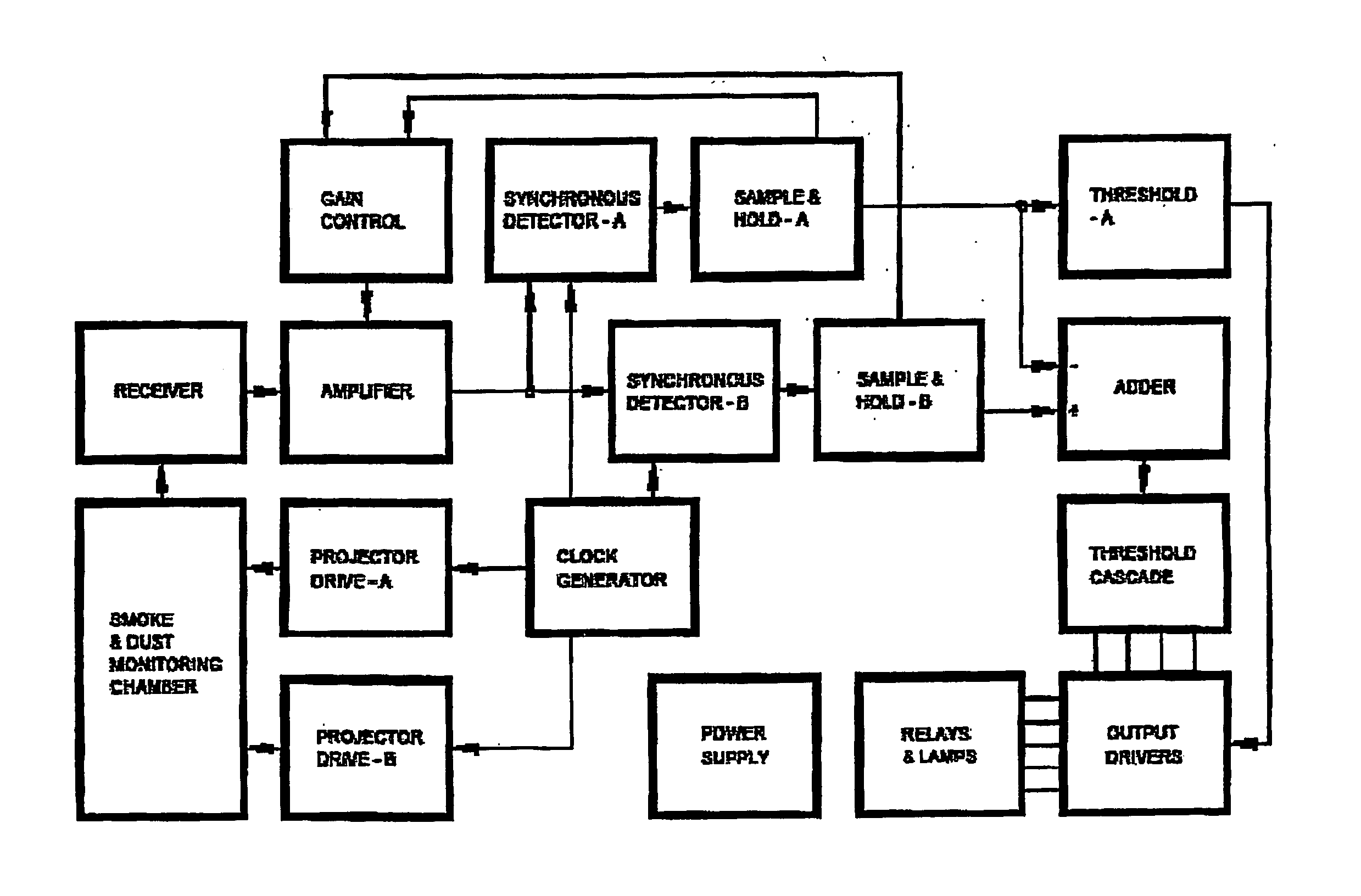
[0057] In the embodiment described, at least two channels are referred to, one being channel A, which uses wavelengths such as red or infrared wavelengths, the other being channel B, which uses wavelengths such as blue wavelengths. Additional channels could be employed such as channel C, which uses wavelengths such as green wavelengths. Other wavelengths may also be employed in accordance with the present invention, as will become apparent in the following description. Generally, it is preferred if a reading established from a longer wavelength is compared with a reading establish from a shorter wavelength. Most preferably, the longer wavelength is subtracted from the shorter wavelength. A ratio may also be used to compare wavelength readings.

Wavelengths of Light

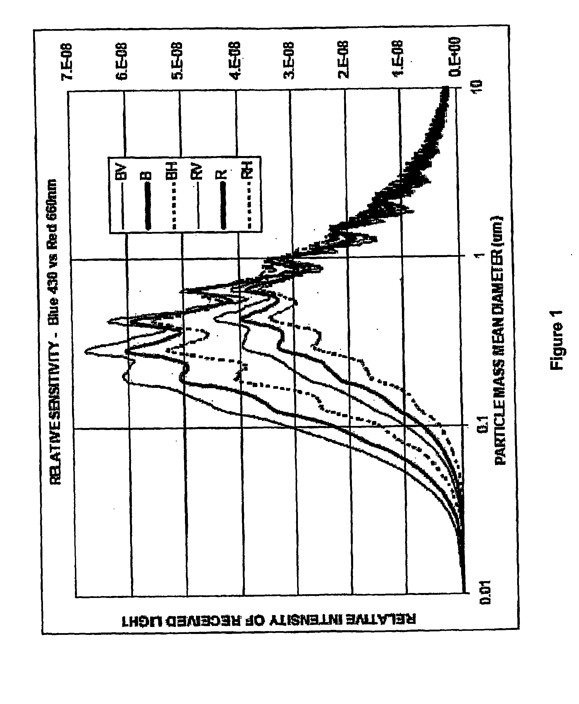
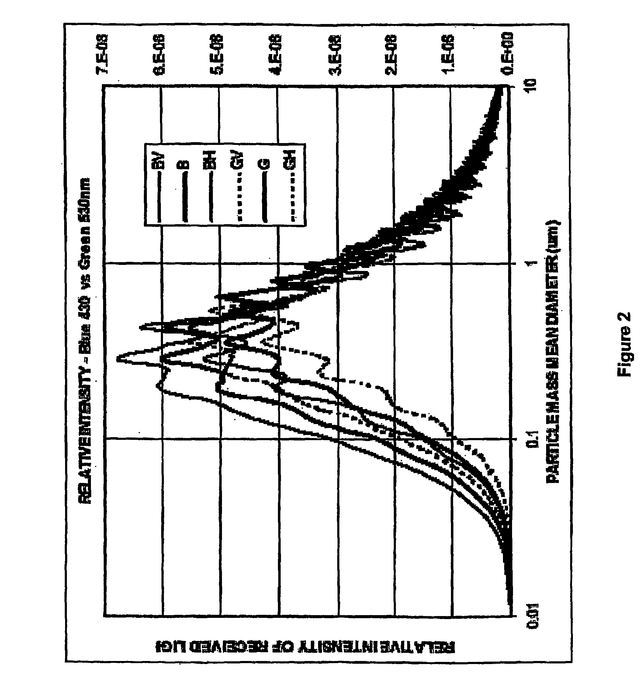
[0058] In one aspect of invention, it has been determined by the present inventor that the wavelengths of light employed have an important bearing on the sensitivity of the present device to particle sizes. The scattering...


PUM


Abstract

The present invention relates to the field of the detection, analysis and/or determination of matter or particles suspended in fluid. In one particular form, the present invention relates to smoke detectors, which detect unwanted pyrolysis or combustion of material. In another form, the present Invention relates to smoke detectors of the early detection type, and which may be applied to ventilation, air-conditioning or duct monitoring of a particular area. In yet another form, the present invention relates to surveillance monitoring, such as building, fire or security monitoring. in still another form, the present invention relates to environment monitoring, such as monitoring, detection and/or analysis of a fluid, zone, area and/or ambient environment, including commercial and Industrial environments.

Description

FIELD OF INVENTION [0001] The present invention relates to the field of the detection, analysis and / or determination of matter or particles suspended In fluid. [0002] In one particular form, the present Invention relates to smoke detectors, which detect unwanted pyrolysis or combustion of material. In another form, the present invention relates to smoke detectors of the early detection type, and which may be applied to ventilation, air-conditioning or duct monitoring of a particular area. In yet another form, the present invention relates to surveillance monitoring, such as building, fire or security monitoring. In still another form, the present invention relates to environment monitoring, such as monitoring, detection and / or analysis of a fluid, zone, area and / or ambient environment, including commercial and industrial environments. [0003] As will become apparent, the present invention has broad application and thus the particular forms noted above are only given by way of example...

Claims


Application Information

Patent Timeline
IPC IPC(8): G08B17/10
CPCG01F1/6842G01N21/53G08B17/12G08B17/10G08B17/107G01P5/10G08B17/113
Inventor COLE, MARTIN TERENCE
Owner SIEMENS SWITZERLAND
Why Eureka
Try Eureka