[0014] It is, therefore, a principal object of this invention to provide a new, useful, and uncomplicated smoke detector having a remote alarm silencing means in the form of a mountable
remote control device but wherein the
remote control device is not hand-held or hard-wired to the smoke detector and which emits electromagnetic
waves of a given frequency to temporarily mute or
silence the audio alarm of the smoke detector and which also allows remote testing of the detector. The remote control device is mountable yet easily relocatable as desired or required by the user. In this way, the silencing means remains in a given location or position where the user will be able to easily locate it and thus easily silence the alarm of the smoke detector. It is another object of the present invention that the remote control device of the present invention, or several of them, be used by the user to remotely silence the alarm of the smoke detector for a short pre-programmed period of time. The smoke detector could be alternatively configured to silence the alarm, reduce the volume of the alarm, and / or activate a visual indicator, such as a light, to indicate that the silencing means has been activated. It is still another object of the present invention to provide a smoke detector having a remote control device that is re-locatable with minimal effort throughout a variety of places within the home. It is still another object to provide a remote silencing device that can come as original equipment with a smoke detector or that can be separately purchased as a replacement unit, the electromagnetic frequency of the replacement unit matching that of the original remote silencing means. The remote control and the smoke detector would allow for “code learning” which allows for selective alarm actuation. It is yet another object of the present invention to provide a remote control device that has its own self-contained long-life battery for allowing the device to generate and transmit an electromagnetic wave, such as an RF
signal, of sufficient energy to be detected by a receiver component within the smoke detector unit, the receiver component silencing the alarm of the smoke detector unit. It is still another object of the present invention to provide a remote control device that is to be used with the smoke detector of the present invention that is aesthetically-pleasing to the user and that may be purchased by the user in a personally-pleasing decorated fashion offered in a wide variety of shapes, colors, patterns and designs or that may be offered with interchangeable housings that come in a wide variety of shapes, colors, patterns and designs.
[0015] The present invention has obtained these objects. It provides for a smoke detector having a remote alarm silencing means wherein the remote means that is used is not hard-wired to the smoke detector and which allows the remote means to be mountable yet easily relocatable as desired or required. That is, the means, or several of them, can be used by the user to remotely silence the alarm of the smoke detector for a short pre-programmed period of time, the remote silencing means being generally re-locatable throughout a variety of places within the area and vicinity of the primary smoke detector unit. The remote alarm silencing means can also be configured to mute or silence the alarm, reduce its
decibel level, and / or activate a visual indicator. The visual indicator could also be used as a means for remote testing of the
operability of the smoke detector.
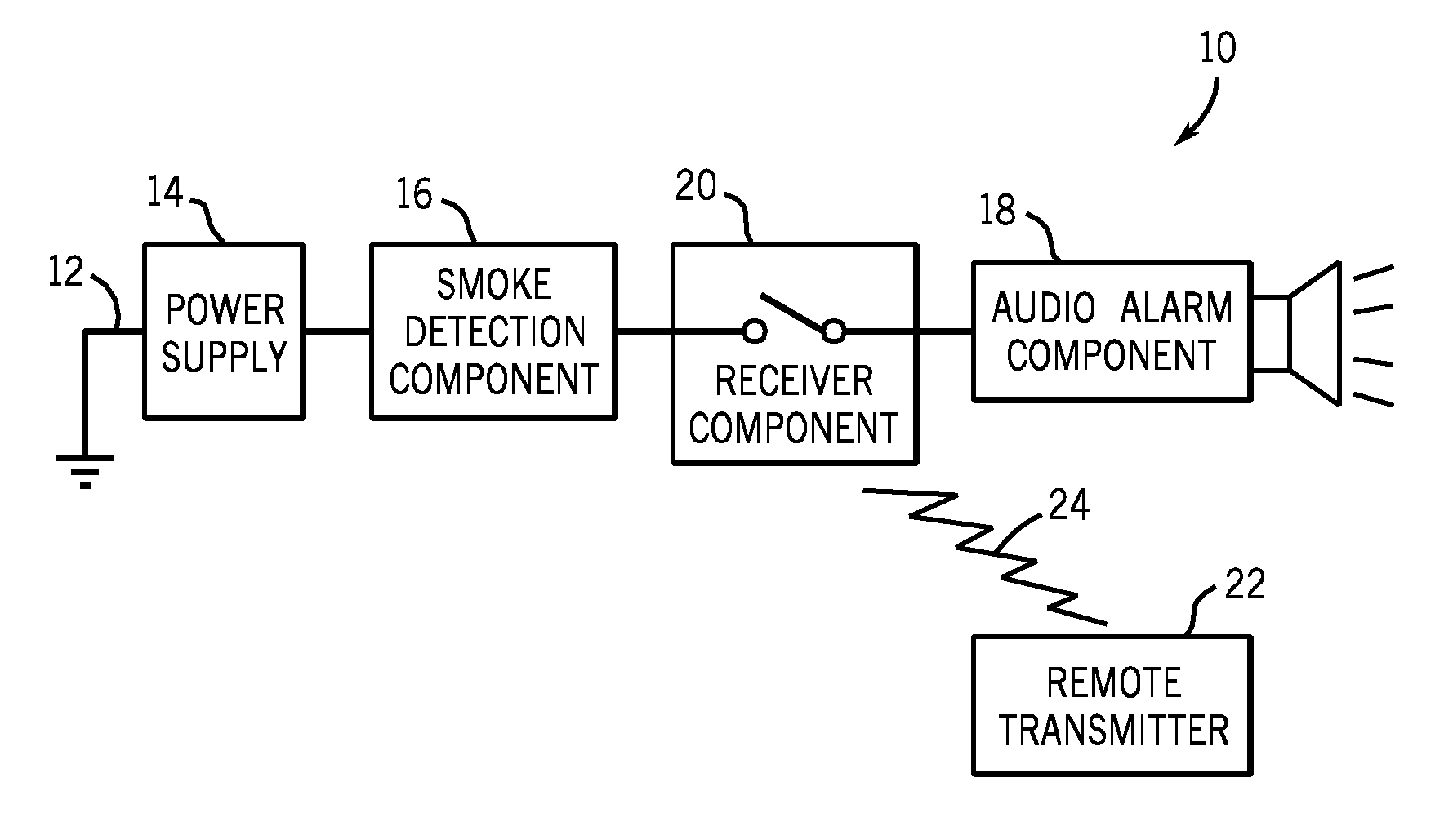
[0017] The present invention is drawn, in its preferred embodiment, to a smoke detector that employs an RF receiver in conjunction with a remote RF transmitter to silence the audible alarm in the event the detector was triggered by nuisance smoke. The smoke detector is mounted to the ceiling in similar fashion as standard
smoke detectors. The remote RF transmitter, however, can be mounted in any convenient location within easy reach of the occupant or user. When the smoke detector sounds an audible alarm due to nuisance smoke, the user can quickly and conveniently press the button on the remote transmitter to silence the audible alarm of the smoke detector for a period of time.
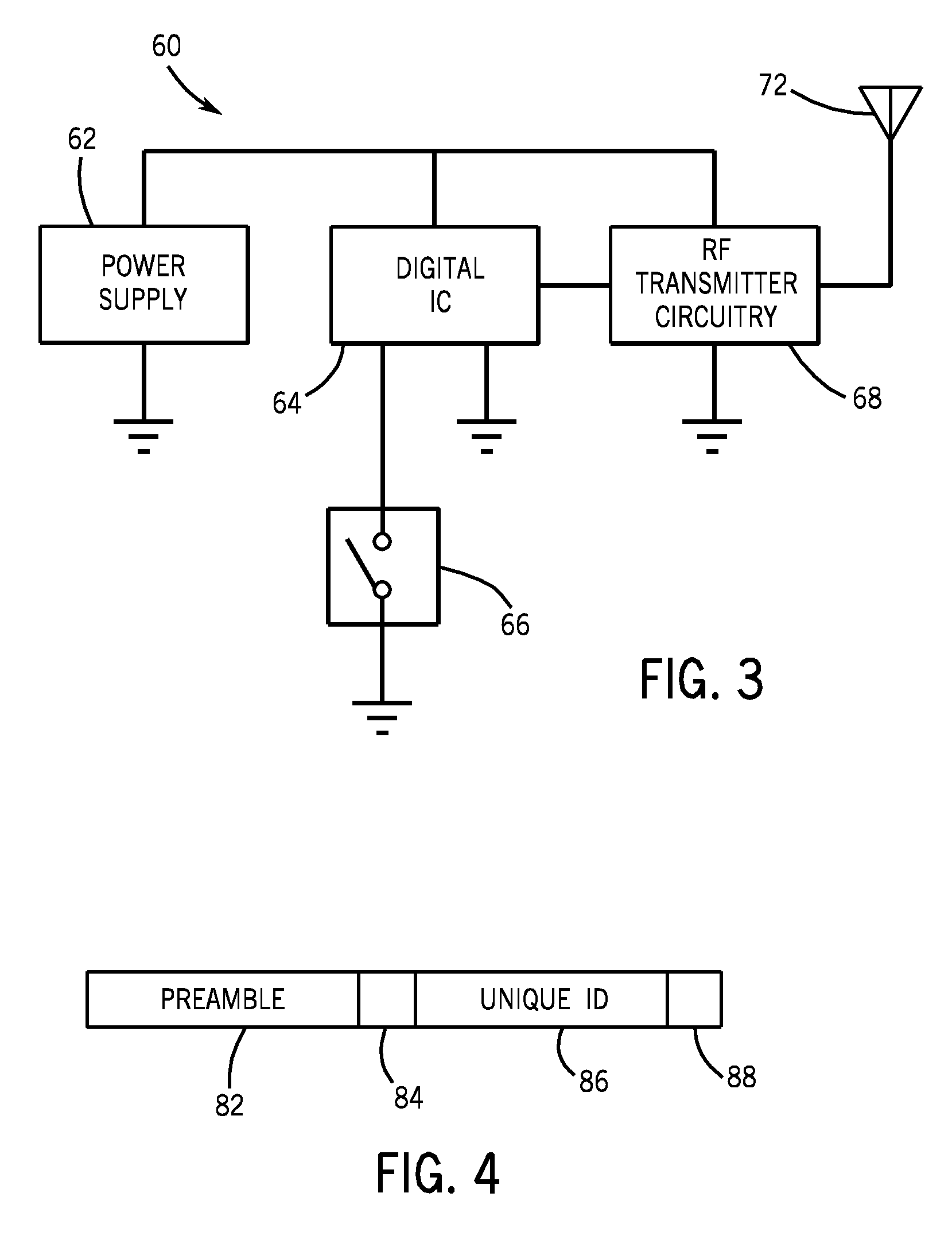
[0018] Additionally, the RF transmitter of the present invention can be programmed with a unique “transmitter identification” or “ID” at the time of manufacture. This unique ID or identification would then be transmitted with each RF message to uniquely identify itself from other RF transmitters. At some time in the manufacturing process, the smoke detector and the remote RF transmitter can be paired in a fashion where the detector “learns” the unique ID of the transmitter and thereby will only silence the audible alarm if it receives an RF message from that particular transmitter. This is critical when several
smoke detectors are installed in a building since a particular remote RF transmitter should only silence the audible alarm on the smoke detector it was intended to silence, not all of the detectors in the building or surrounding area. This unique ID also allows multiple RF transmitters to operate on the same RF frequency, thus greatly simplifying the manufacturing process.
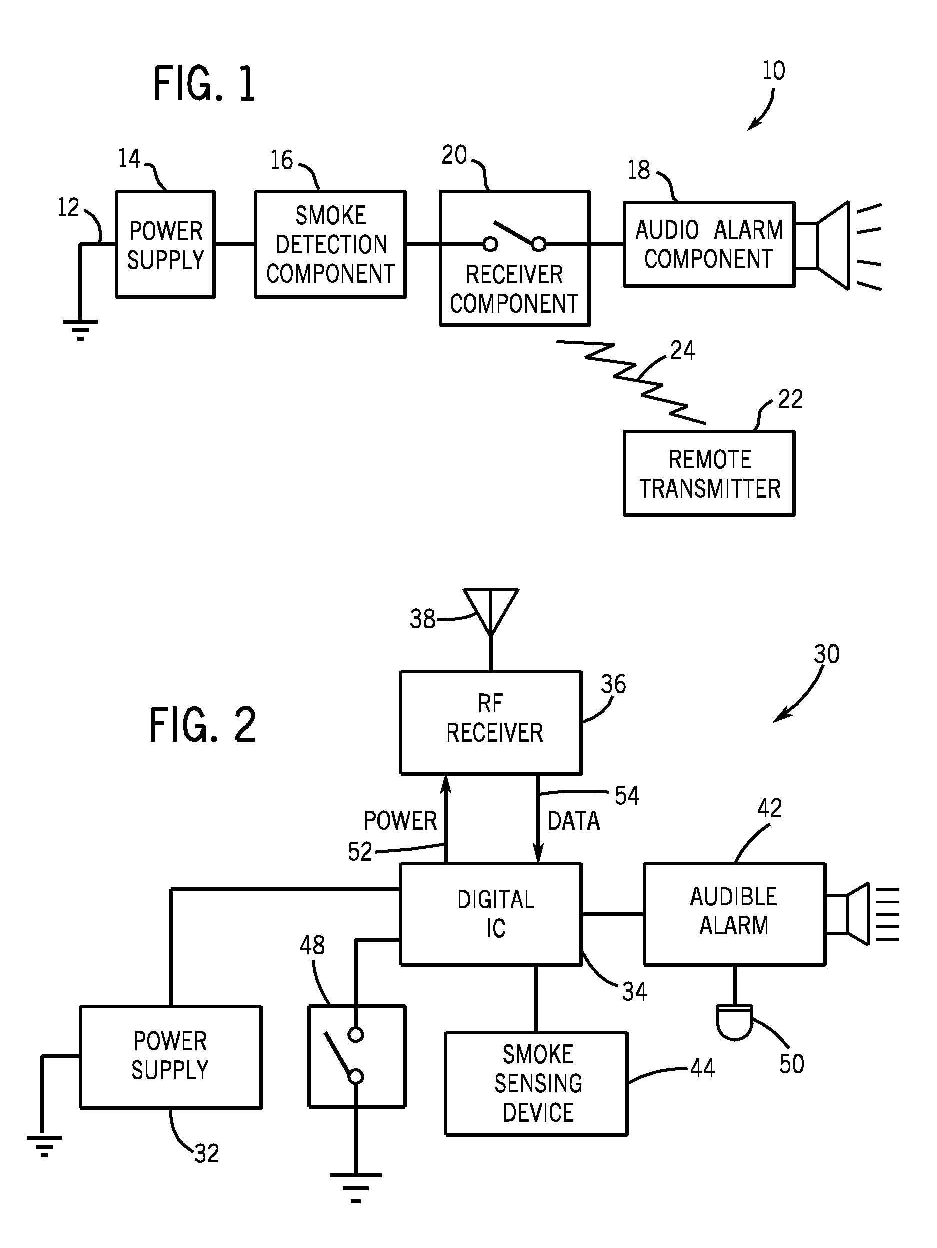
[0019] To eliminate increased
power consumption due to the RF receiver being required to “listen” for incoming RF messages, the present invention also implements means to activate the RF receiver only when the audible alarm has been activated. Once the audible alarm has been silenced or deactivated by the detector, the RF receiver would also be deactivated or put into a “sleep” mode. This approach absolutely minimizes
energy consumption of the battery without compromising the “silence” feature of the present invention. As an example, if the RF receiver was allowed to operate continuously, it could very well receive an RF message from an RF transmitter with an ID that matched the ID stored within the detector. If this RF message was received when no audible alarm was active, the detector would not perform any function after
receipt of the RF message (i.e., there is no alarm to silence). So there is no need to listen for RF messages unless the audible alarm is active anyway. In this regard, the smoke detector of the present invention allows the RF receiver to continuously “listen” for incoming RF messages only upon the occurrence of an alarm status within the smoke detector.

