
Antenna system

a technology of antennas and antennas, applied in the field of antenna systems, can solve the problems of large space, large size, and complex manufacturing processes, and achieve the effect of reducing the number of antennas for receiving uhf and vhf bands and requiring large mounting spa

Inactive Publication Date: 2005-02-22
DX ANTENNA CO LTD
View PDF25 Cites 77 Cited by
  • Summary
  • Abstract
  • Description
  • Claims
  • Application Information

AI Technical Summary

Benefits of technology

An antenna system according to one embodiment of the present invention includes a dipole antenna for a first frequency band. The dipole antenna has a pair of rod elements arranged substantially in a straight line. The antenna system also includes a Yagi antenna

Problems solved by technology

An Alford loop antenna and a cloverleaf antenna are formed of many components, are large in size and require complicated manufacturing processes.
Accordingly, such antennas for receiving UHF and VHF bands undesirably require a large space to mount them because they are large.
In addition, non-directional antennas, such as Alford loop antennas and cloverleaf antennas, are subject to receiving undesired radio waves and, therefore, tend to cause ghosts to appear in a television picture when used for receiving television broadcast ratio waves.

Method used


Image

  • Antenna system
  • Antenna system
  • Antenna system

Examples


sixth embodiment

An antenna system according to the present invention is described with reference to FIGS. 23-37.

The antenna system has a body 202 as shown in FIG. 23. The body 202 is generally octagonal and flat in shape. As shown in FIG. 24, the body 202 has slightly convex sides 204a, 204b, 204c and 204d, which are angularly spaced one another by 90°. Between adjacent ones of the convex sides 204a-204d, the body 202 also has concave sides 206a, 206b, 206c and 206d. The concave sides 206a-206d connect adjacent ones of the convex sides 204a-206d.

As shown in FIG. 24A, within the body 202, disposed are a plurality, e.g. four, of Yagi antennas 208a, 208b, 208c and 208d for a first frequency band, e.g. the UHF band. Two of the four Yagi antennas, e.g. the Yagi antennas 208a and 208c, are disposed on a line 210a connecting the opposing convex sides 204a and 204c, in one plane, for example, in a horizontal plane. The other two Yagi antennas 208b and 208d are disposed on a line 210b extending orthogonal ...


PUM


Abstract

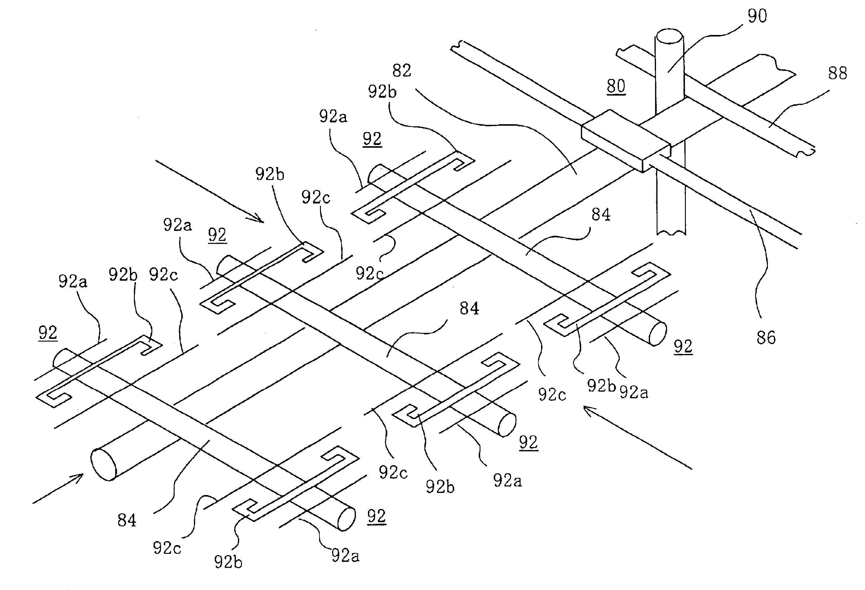
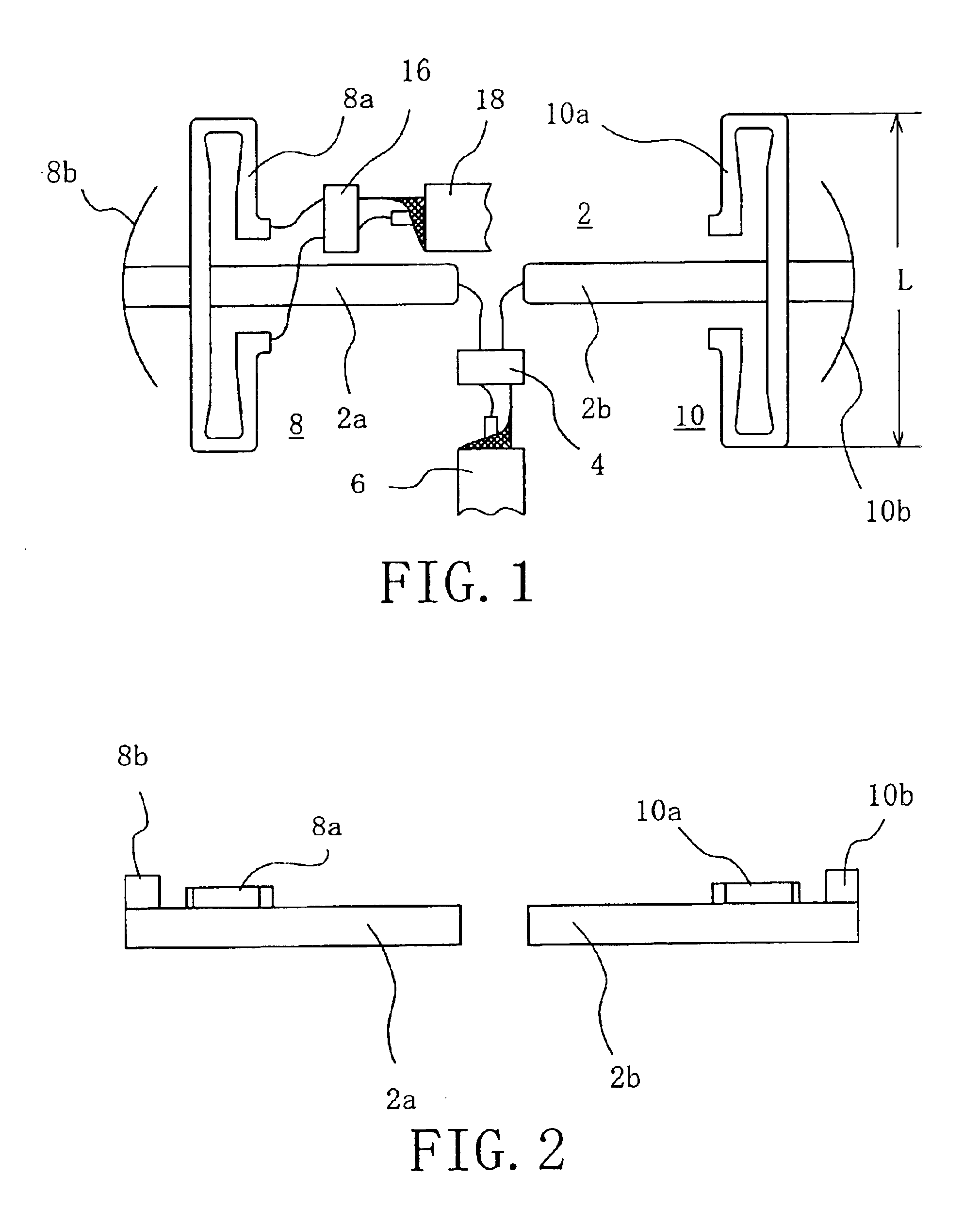
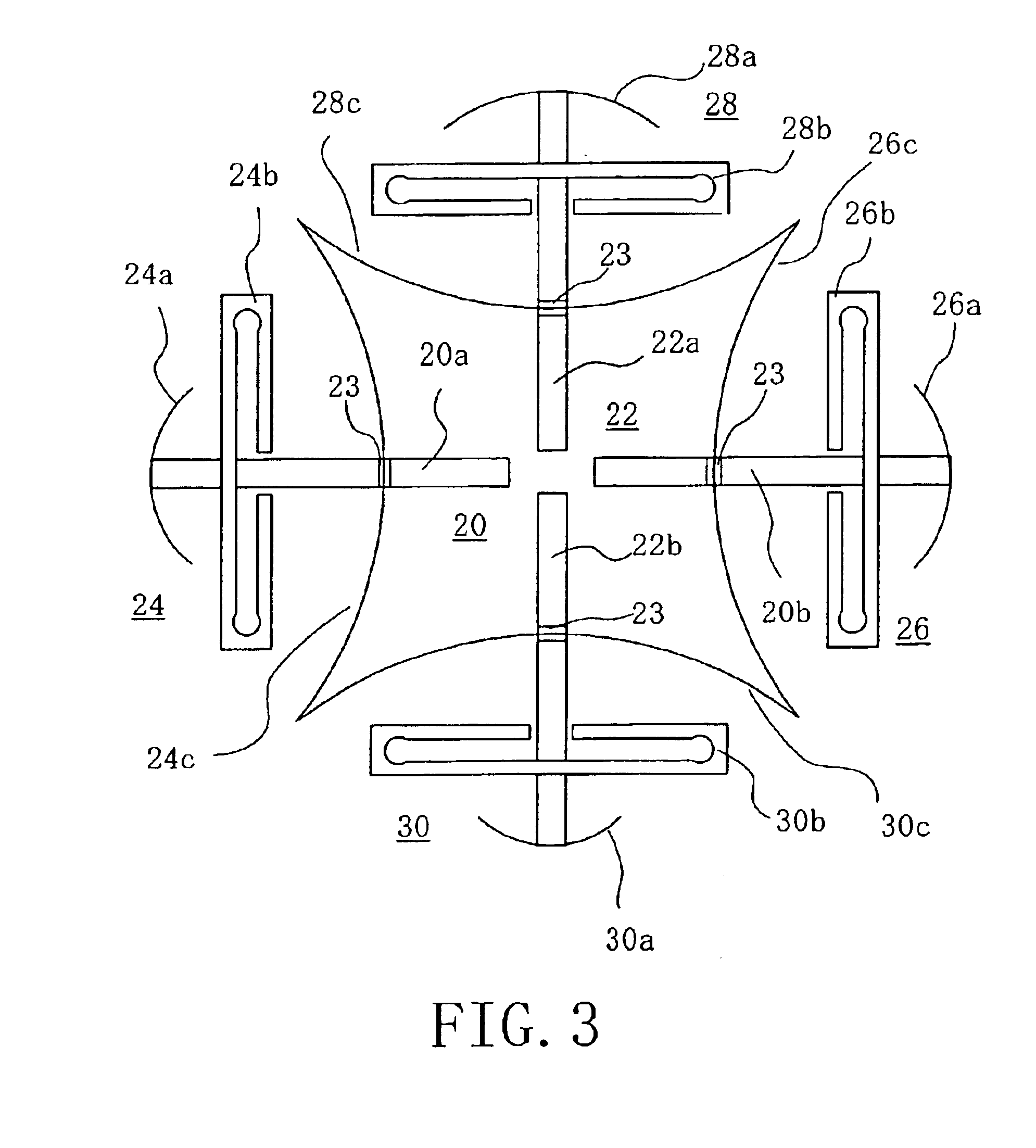
An antenna system includes a VHF dipole antenna having a pair of rod elements disposed substantially in a line, and a UHF Yagi antenna having a radiator and a director disposed on the rod elements.

Description

This invention relates to an antenna system.BACKGROUND OF THE INVENTIONAntennas mounted on a moving article, such as a television broadcast receiving antenna mounted on a car, may be non-directional. Non-directional antennas include, for example, an Alford loop antenna and a cloverleaf antenna. To receive radio waves in, for example, VHF and UHF bands by means of such non-directional antennas, one for each of the frequency bands has been used.An Alford loop antenna and a cloverleaf antenna are formed of many components, are large in size and require complicated manufacturing processes. Accordingly, such antennas for receiving UHF and VHF bands undesirably require a large space to mount them because they are large. In addition, non-directional antennas, such as Alford loop antennas and cloverleaf antennas, are subject to receiving undesired radio waves and, therefore, tend to cause ghosts to appear in a television picture when used for receiving television broadcast ratio waves.An ob...

Claims


Application Information

Patent Timeline
IPC IPC(8): H01Q21/24H01Q5/00H01Q21/28H01Q9/04H01Q19/00H01Q9/26H01Q19/30H01Q21/00H01Q9/20H01Q3/24H01Q5/40
CPCH01Q3/242H01Q9/20H01Q9/26H01Q5/40H01Q21/24H01Q21/28H01Q19/30
Inventor HORII, SHOTARO
Owner DX ANTENNA CO LTD
Learn More