Rotating radius limiter for cable management panel and methods

a technology of limiters and cable management, applied in the direction of optics, fibre mechanical structures, instruments, etc., can solve the problems of unnecessary or excessive displacement of optical fiber cables, attenuation and loss of signal strength, and subject to bending and other forces

Inactive Publication Date: 2005-03-08
COMMSCOPE TECH LLC
View PDF45 Cites 186 Cited by
  • Summary
  • Abstract
  • Description
  • Claims
  • Application Information

AI Technical Summary

Benefits of technology

In preferred embodiments, the drawer assembly includes a chassis and a drawer, with the drawer being slidably mounted within the chassis. Further, in preferred embodiments, there is a control mechanism secured to the drawer assembly to synchronize slidable movement of the cable radius limiter relative to the slidable movement of the drawer within the chassis. Preferably, the cable radius limiter is pivotally mounted to the control mechanism to permit pivoting of the radius limiter relative to the drawer assembly.

Problems solved by technology

When moving the trays or drawers, unnecessary or excessive displacement of the optical fiber cables is undesirable.
As the optical fiber cables are displaced, they are subject to bending and other forces.
Bending of the fibers can cause attenuation and loss of signal strength.
As the fiber bends, the fiber can also break, resulting in a loss of transmission through the fiber.

Method used


Image

  • Rotating radius limiter for cable management panel and methods
  • Rotating radius limiter for cable management panel and methods
  • Rotating radius limiter for cable management panel and methods

Examples


Embodiment Construction

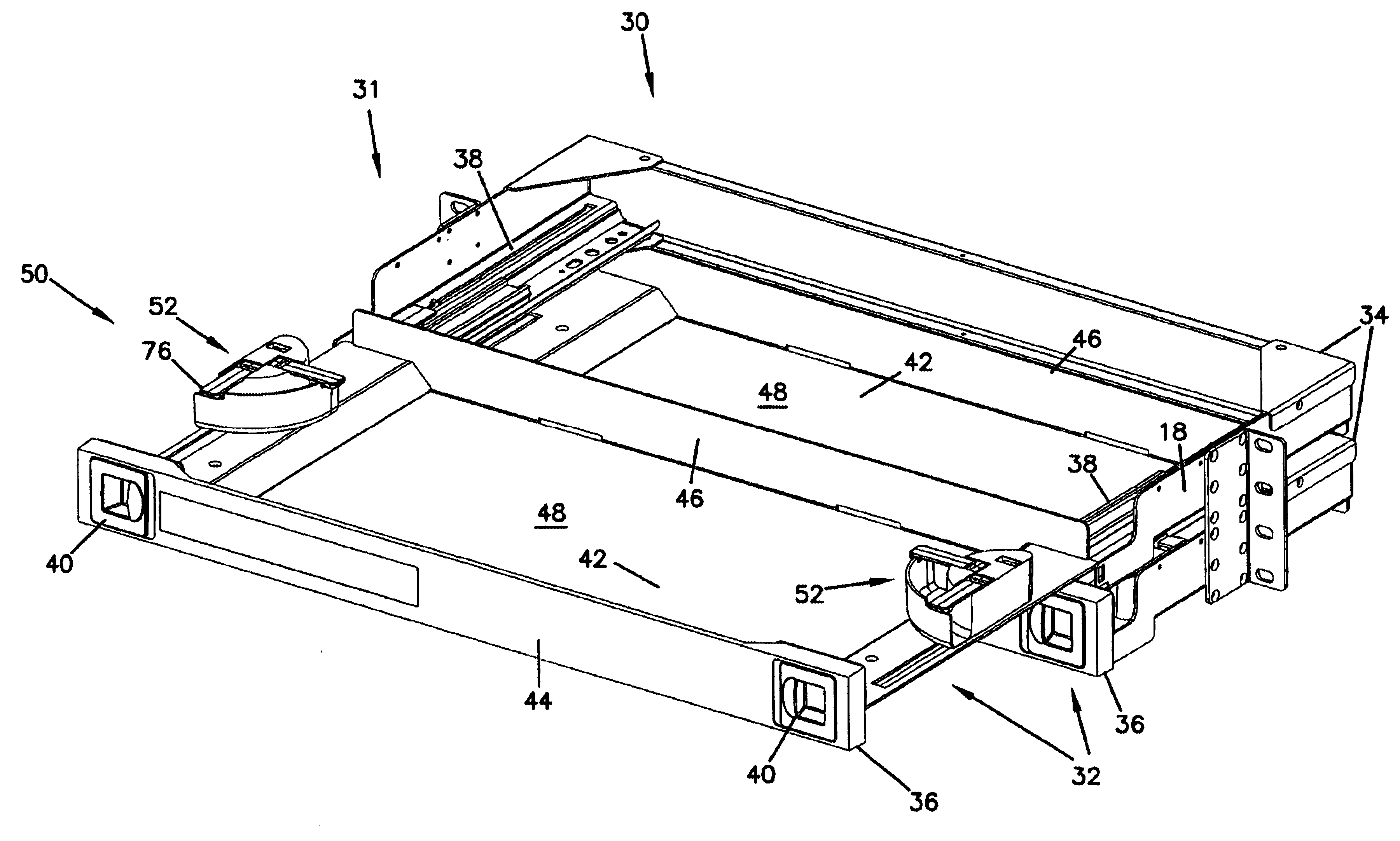
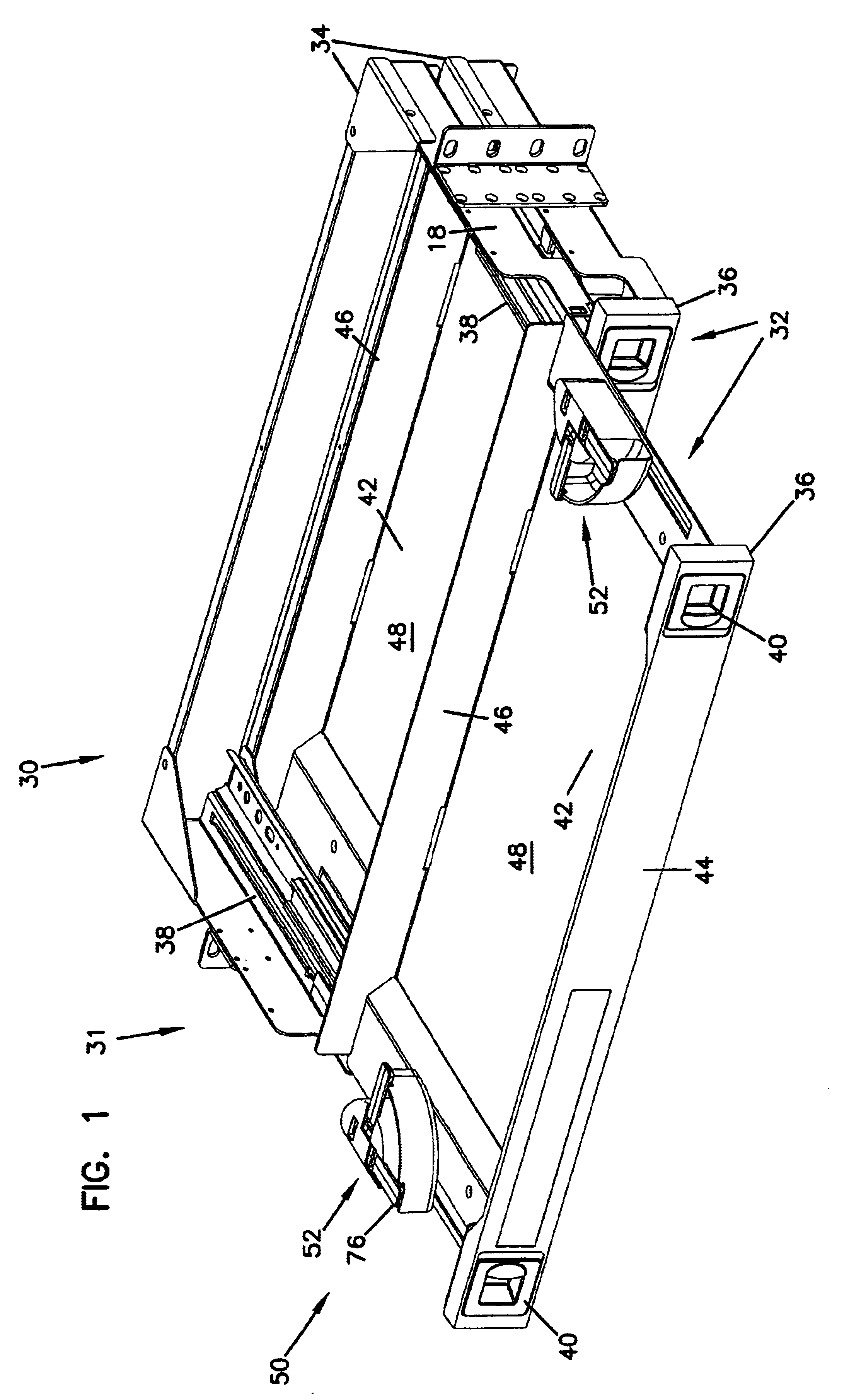
A cable management panel or module is depicted in FIG. 1 generally at 30. In the one shown, the panel 30 includes a plurality of drawer assemblies 32. In the one shown in FIG. 1, the panel 30 includes two drawer assemblies 32. Each of the drawer assemblies 32 includes a chassis 34 and a drawer 36 slidably mounted within the chassis 34.

Each drawer 36 may include cable management structure, for example, devices for storing the cables or connecting the cables to other cables or fiber optic devices, such as attenuators, couplers, switches, wave division multiplexers, splitters or splices. Drawers 36 are slidable relative to the chassis 34 by way of two drawer slides 38 on opposite sides of the chassis 34. In the particular embodiment shown, each drawer 36 includes two latches 40 to secure the drawer 36 in a closed position.

Each drawer 36 includes a base 42, a front wall 44, and a rear wall 46. Note that the drawer 36 is absent side walls, or is “side wall free.” This structure allows fo...


PUM


Abstract

A rotating radius limiter for an optical fiber cable management panel is provided. The radius limiter includes a radius limiter structure and a bracket that permit relative motion between the structure and the bracket. The structure and bracket are mounted to a sliding cable management panel. The radius limiter structure includes a curved wall, an opening for receiving cables and a trough section for retaining cables about a radius portion.

Description

TECHNICAL FIELDThis disclosure concerns management of optical fiber cables. In particular, this disclosure relates to storage of optical fiber cables and devices in the telecommunications industry.BACKGROUNDCable termination, splice, and storage devices are known including, for example, devices shown in U.S. Pat. Nos. 4,792,203 and 5,946,440, both assigned to ADC Telecommunications, Inc. Both of these patents concern devices with movable trays for storage and management of the optical fiber cables. U.S. Pat. No. 5,066,149, also assigned to ADC Telecommunications, concerns a cable management device including slidable drawers, each including a cable slack take-up mechanism. When moving the trays or drawers, unnecessary or excessive displacement of the optical fiber cables is undesirable. As the optical fiber cables are displaced, they are subject to bending and other forces. Bending of the fibers can cause attenuation and loss of signal strength. As the fiber bends, the fiber can also...

Claims


Application Information

Patent Timeline
Patent Type & Authority Patents(United States)
IPC IPC(8): G02B6/44
CPCG02B6/4455
Inventor MERTESDORF, DANIEL R.
Owner COMMSCOPE TECH LLC
Why Eureka
Try Eureka