
Low leak pressure control actuator

Inactive Publication Date: 2005-03-15
DELPHI TECH INC
View PDF12 Cites 23 Cited by
  • Summary
  • Abstract
  • Description
  • Claims
  • Application Information

AI Technical Summary

Benefits of technology

Preferably, the actuator further includes a frame and the housing extends from the frame. A coil is disposed within the frame and is energizable to move the actuator between the partially energized configurations and the fully energized configuration. Also, an armature is slidably disposed within the coil. The armature defines a proximal end and a distal end that engages the poppet. A collar surround the distal end of the armature. Moreover, in a preferred embodiment, a first diaphragm spring circumscribes the distal end of the armature adjacent to the collar and biases the actuator to the de-energized configuration. Preferably, a second diaphragm spring circumscribes the proximal end of the armature and helps bias the actuator to the de-energized configuration.

Problems solved by technology

Further, in the partially energized configurations, incremental changes in the displacement of the poppet produce incremental changes in a control pressure.

Method used


Image

  • Low leak pressure control actuator
  • Low leak pressure control actuator
  • Low leak pressure control actuator

Examples


Embodiment Construction

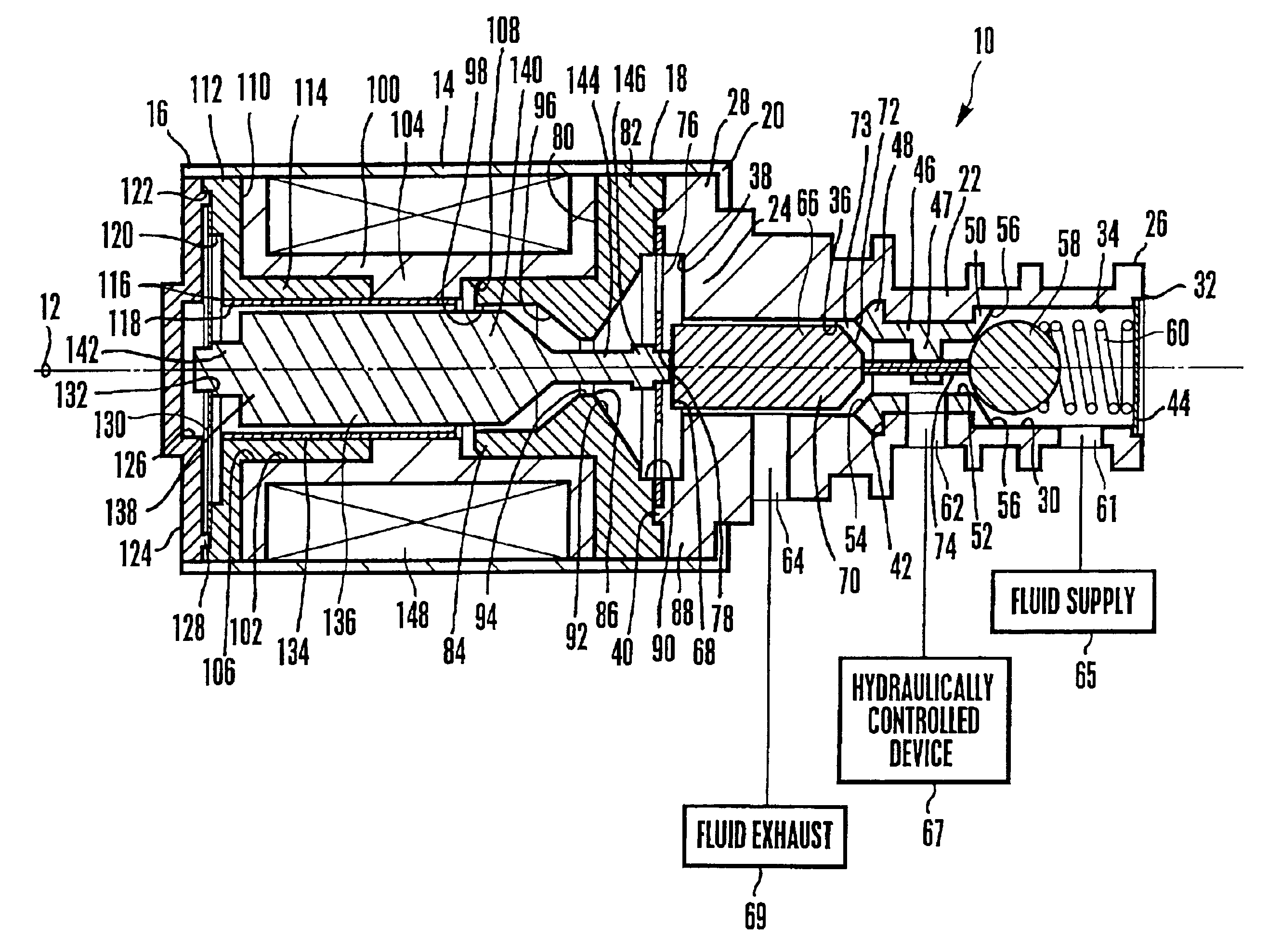
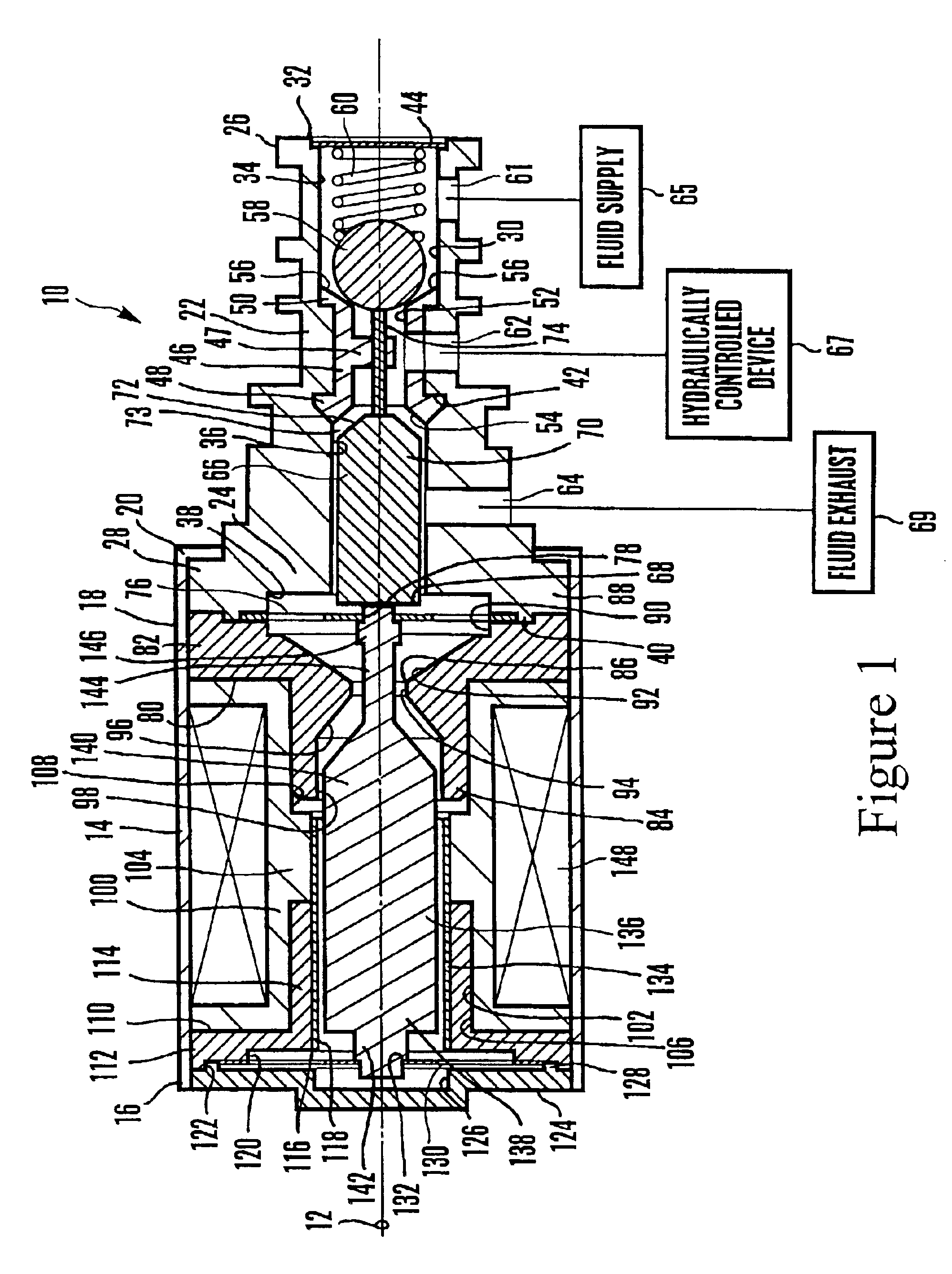
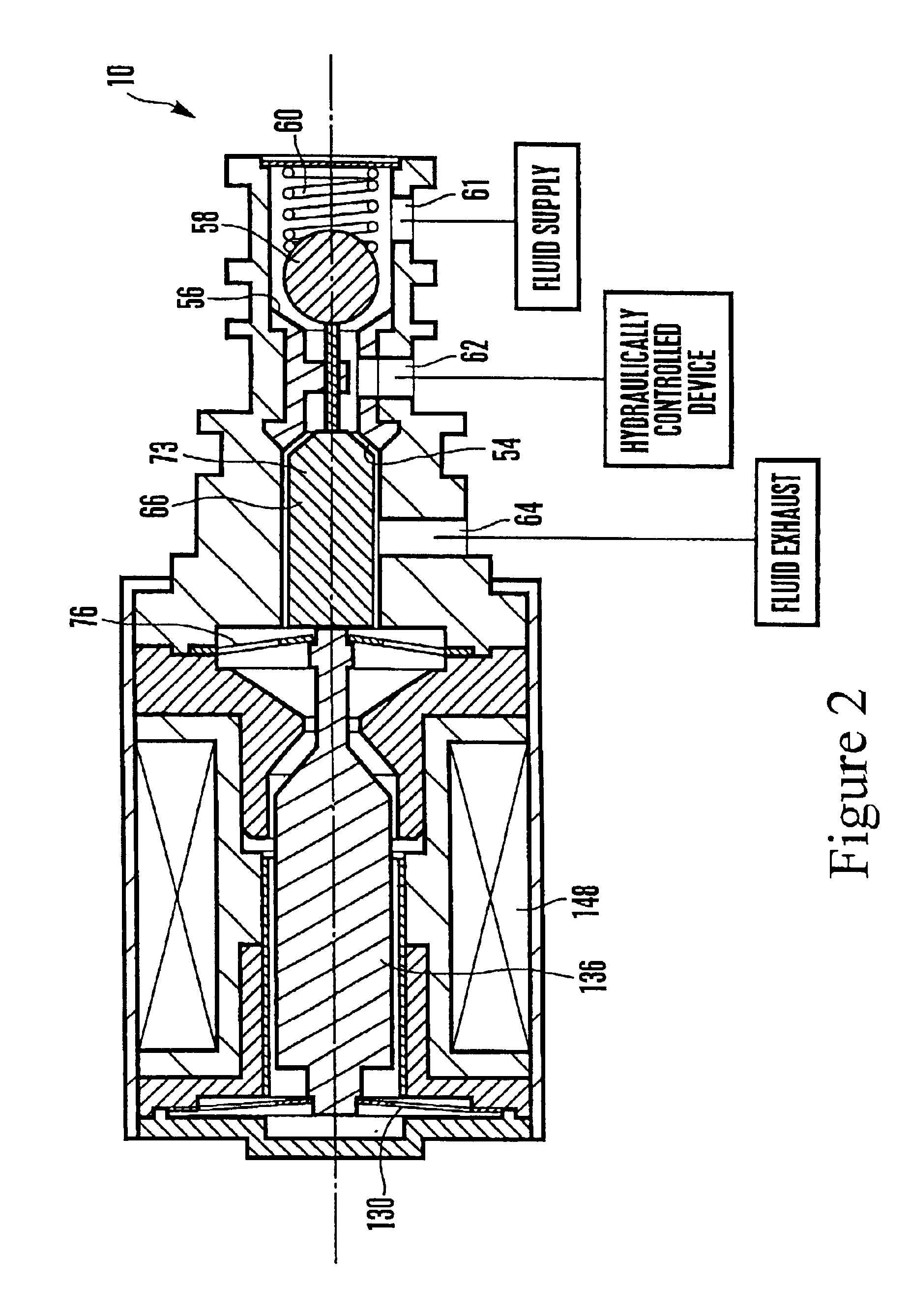
Referring to the Figures, a low leak pressure control actuator is shown and generally designated 10. As shown, the actuator 10 defines a longitudinal axis 12 and includes a hollow, generally cylindrical frame 14 that defines an open proximal end 16 and an open distal end 18 that is circumscribed by an internal lip 20. The Figures show that the actuator 10 includes also includes a housing 22 that defines a proximal end 24 and a distal end 26. The proximal end 24 of the housing 22 is circumscribed by a flange 28 that has an external diameter approximately equal to the internal diameter of the frame 14. The housing 22 is disposed within the frame 14 such that the distal end 26 of the housing 22 protrudes through and extends beyond the distal end 18 of the frame 14. Also, the flange 28 of the housing 22 abuts the internal lip 20 of the frame 14.

Moreover, the Figures show that a generally cylindrical bore 30 can be formed through the housing 22 along the longitudinal axis 12. The bore 30...


PUM


Abstract

A low leak pressure control actuator for, e.g., controlling pressure in an automatic transmission system, includes a poppet and a check ball slidably disposed within a housing. The poppet and check ball are movable between a de-energized configuration, plural partially energized configurations, and a fully energized configuration. In the de-energized configuration, the poppet and check ball prohibit all flow to and from the supply port and permit flow between the control port and the exhaust port. In the partially energized configurations, the poppet and check ball permit flow to and from all of the ports, and incremental changes in the internal displacement of the poppet produce incremental changes in a control pressure. In the fully energized configuration flow, the poppet and check ball prohibit all flow to the exhaust port and permit fluid flow between the supply port and the control port.

Description

TECHNICAL FIELDThe present invention relates to motor vehicle sensors and actuators.BACKGROUND OF THE INVENTIONAutomobiles equipped with automatic transmissions have become ubiquitous. A conventional automatic transmission includes a planetary gearset, a set of bands used to engage parts of the gearset, a set of wet-plate clutches to engage other parts of the gears, a hydraulic system controlling the clutches and bands, and a transmission fluid pump. Numerous solenoid valves or actuators are used to control the flow of transmission fluid through the automatic transmission. The typical solenoid valves that are used in an automatic transmission include variable bleed solenoid (VBS) valves and variable flow solenoid (VFS) valves.A VBS valve is a current-controlled, electro-hydraulic actuator that provides an outlet pressure that is a precise function of the current applied to the valve. A constant supply pressure is supplied to the valve through a fixed control orifice to a control cha...

Claims


Application Information

Patent Timeline
IPC IPC(8): G05D16/20
CPCG05D16/2013G05D16/2024Y10T137/87217
Inventor AVILA, MIGUEL I.
Owner DELPHI TECH INC
Learn More