Downhole safety valve for central circulation completion system

a safety valve and completion system technology, applied in the direction of sealing/packing, borehole/well accessories, fluid removal, etc., can solve the problem that the general use of the central circulation completion system cannot be achieved

Inactive Publication Date: 2005-03-15
FMC TECH INC
View PDF24 Cites 13 Cited by
  • Summary
  • Abstract
  • Description
  • Claims
  • Application Information

AI Technical Summary

Problems solved by technology

However, since most downhole safety valves are designed to be used with conventional completion systems, wherein well fluids are communicated through the inner tubing string, they generally cannot be used with central circulation completion systems.

Method used


Image

  • Downhole safety valve for central circulation completion system
  • Downhole safety valve for central circulation completion system
  • Downhole safety valve for central circulation completion system

Examples


Embodiment Construction

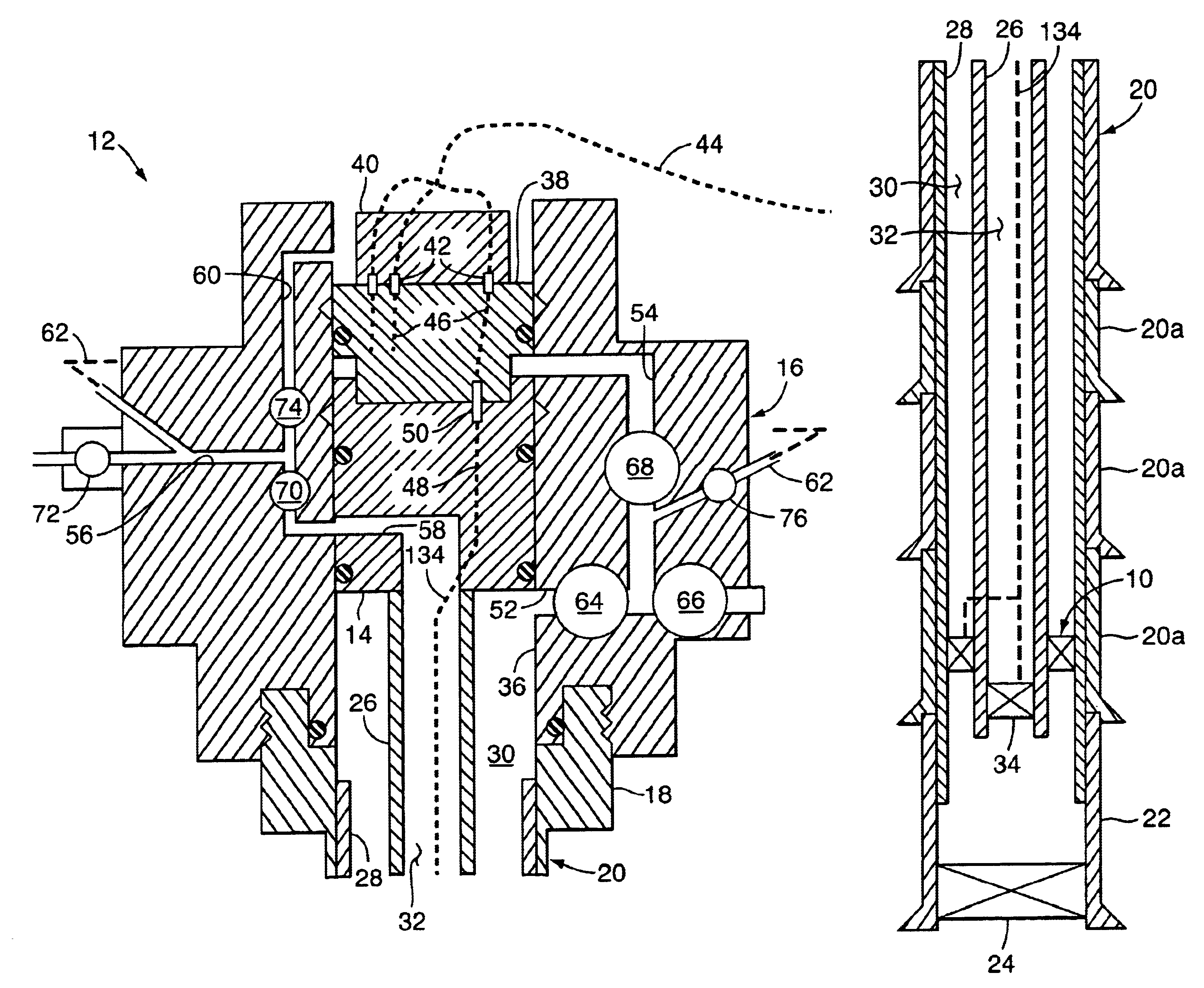
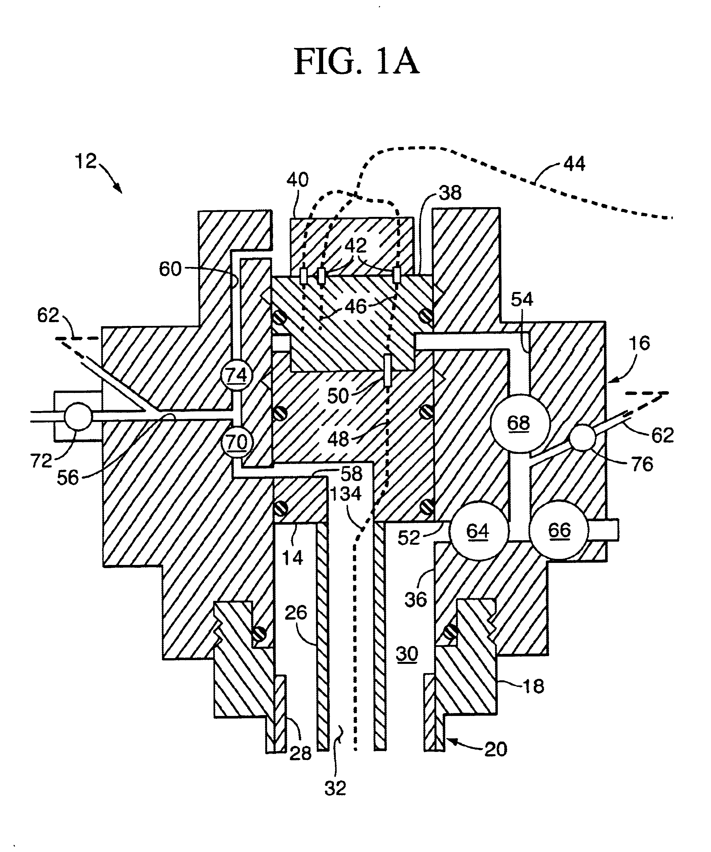
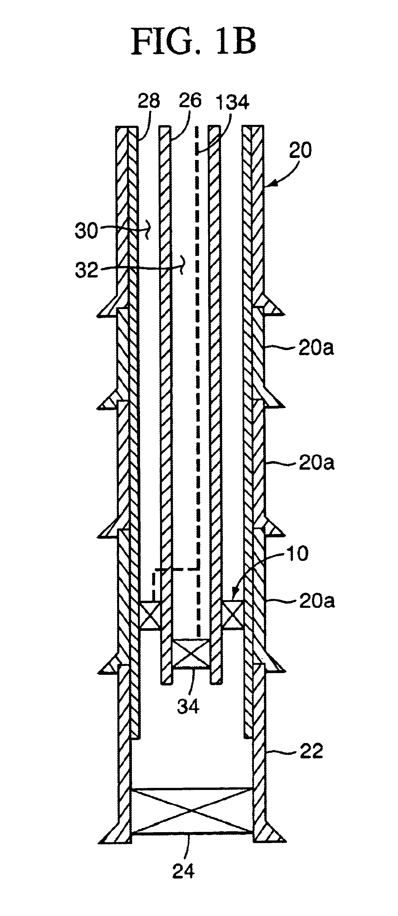
Referring to FIGS. 1A and 1B, the downhole safety valve of the present invention, generally 10, is shown installed in an exemplary central circulation completion system 12. As described in the aforementioned International Publication Number WO 01 / 81710 A1, a central circulation completion system can take many forms. In the embodiment shown in FIGS. 1A and 1B, for example, the central circulation completion system 12 comprises a tubing hanger 14 which is supported in a christmas tree 16 that is installed on a wellhead housing 18. The wellhead housing 18 in turn is mounted to the top of a casing string 20 which extends into the hydrocarbon reservoir. The casing string 20 may comprise a number of sections of expandable casing 20a, each of which is successively installed using conventional methods. In addition, a liner section 22 comprising a liner top isolation valve 24 may be installed below the lowermost section of expandable casing 20a.

The exemplary central circulation completion s...


PUM


Abstract

A downhole safety valve for a central circulation completion system having concentric inner and outer tubular members defining a production bore therebetween comprises a generally cylindrical body which includes an outer surface which is sealed to the outer tubular member and an axial through bore to which the inner tubular member is secured. In this manner, the downhole safety valve forms a pressure barrier between a first portion of the production bore located below the body and a second portion of the production bore located above the body. The downhole safety valve further comprises at least one flow passage which extends through the body and communicates between the first and second portions of the production bore, and at least one closure member which is disposed across the flow passage to control fluid flow between the first and second portions of the production bore.

Description

BACKGROUND OF THE INVENTIONThe present invention relates to a downhole safety valve for a central circulation completion system. More particularly, the invention relates to a valve for selectively sealing the annular production bore between the inner tubing string and the outer tubing string in a central circulation completion system.In traditional subsea completion systems, a tubing string is suspended from a tubing hanger which is landed in a wellhead housing or in a christmas tree that is installed over the wellhead housing. The tubing string extends into the hydrocarbon reservoir and defines a production bore through which well fluids may be produced. In addition, the tubing string is usually positioned within a casing string which is typically suspended from the wellhead housing. The casing string also extends into the reservoir, and the annulus between the tubing string and the casing string defines a service bore through which fluids may be circulated, for example during inst...

Claims


Application Information

Patent Timeline
Patent Type & Authority Patents(United States)
IPC IPC(8): E21B34/00E21B34/10
CPCE21B34/10
Inventor SKEELS, HAROLD B.
Owner FMC TECH INC
Why Eureka
Try Eureka