Zoomable spot module

a spot module and zoom technology, applied in the field of zoomable spot modules, can solve the problems of significant beam non-uniformity, individual leds are typically insufficiently bright for most lighting applications, and the spot ights of the mr-series do not include adjustable beams

Inactive Publication Date: 2005-03-15
GELCORE LLC (US)
View PDF5 Cites 192 Cited by
  • Summary
  • Abstract
  • Description
  • Claims
  • Application Information

AI Technical Summary

Problems solved by technology

However, the MR-series spot ights do not include adjustable beams.
This arrangement suffers from significant beam non-uniformity when the light source is strongly defocused.
In spite of continuing improvements in LED light output, at present an individual LED is typically insufficiently bright for most lighting applications.
Nonetheless, due to the small size of LED's, this intensity limitation can be obviated through the use of a plurality of closely packed LED's that cooperate to produce sufficient light.
Application of LED's to spotlighting applications, and especially to spotlighting applications in which the LED-based lamp is contemplated as a retrofit for replacing an existing lamp that employs another lighting technology (e.g., a retrofit for replacing an MR-series halogen lamp) is complicated by the use of multiple LED's as the light source.
The spatially distributed nature of an LED source array greatly reduces the effectiveness of conventional parabolic reflectors which are designed to collimate and direct light emanating from a point source, such as light generated by a halogen or incandescent bulb filament.
Furthermore, a front lens of the type optionally included in an MR-series halogen spot lamp is ill-suited for collimating light from a plurality of LED's, because most of the LED's are not positioned on the optical axis of the lens.
Thus, the optical systems of existing spot lamps, both with and without variable beam angle, are relatively ineffective when used in conjunction with LED light sources.

Method used


Image

  • Zoomable spot module
  • Zoomable spot module
  • Zoomable spot module

Examples


Embodiment Construction

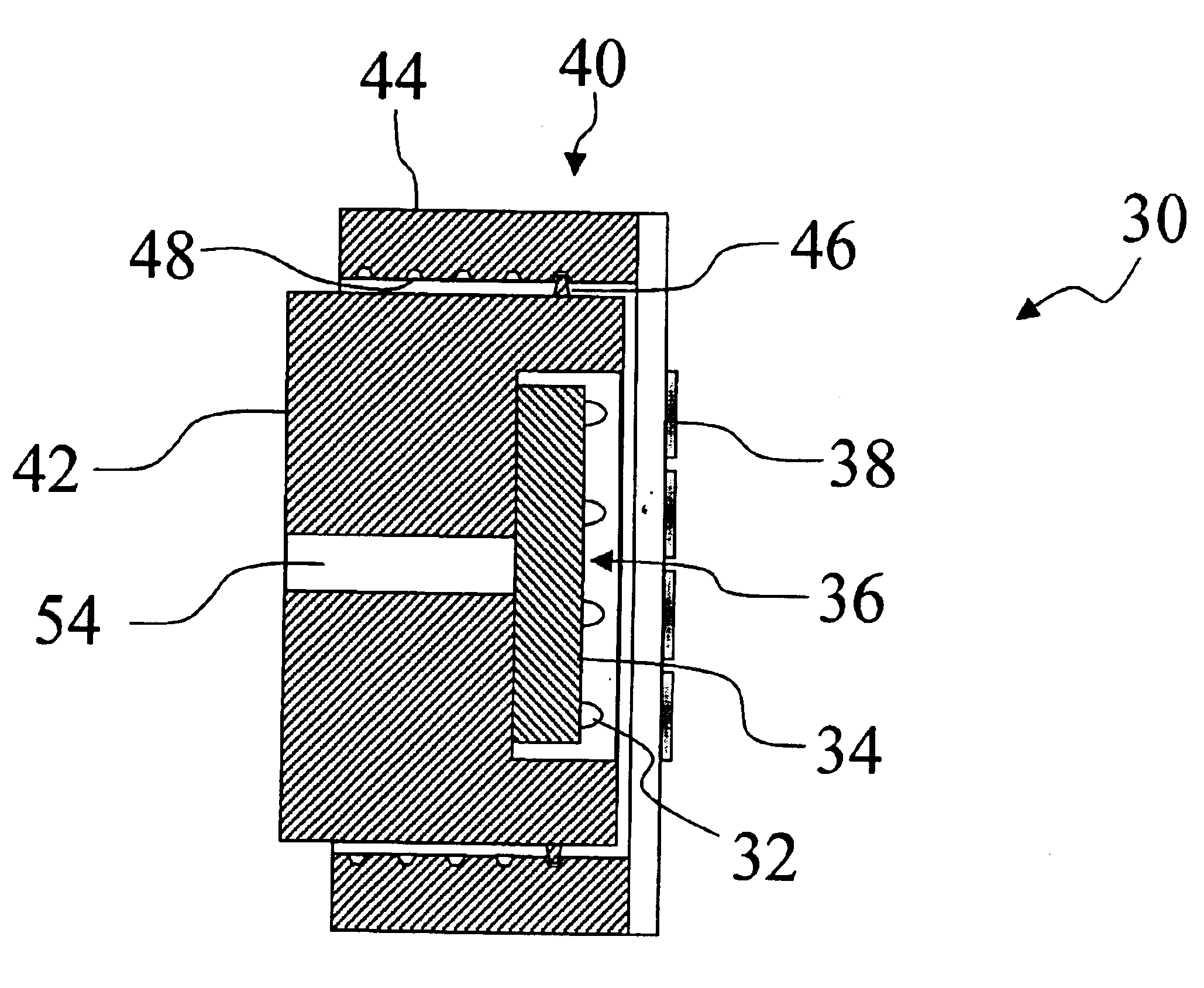
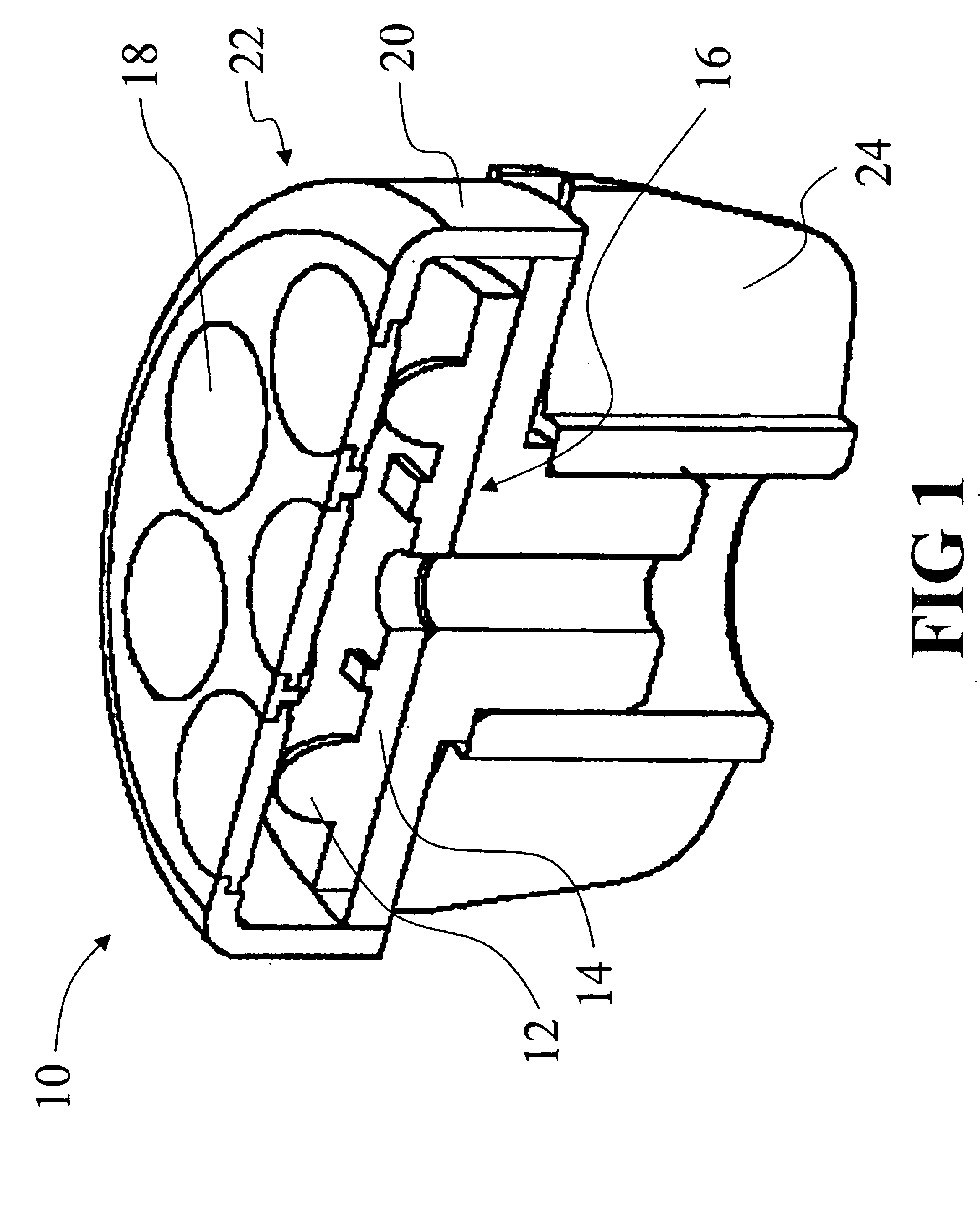
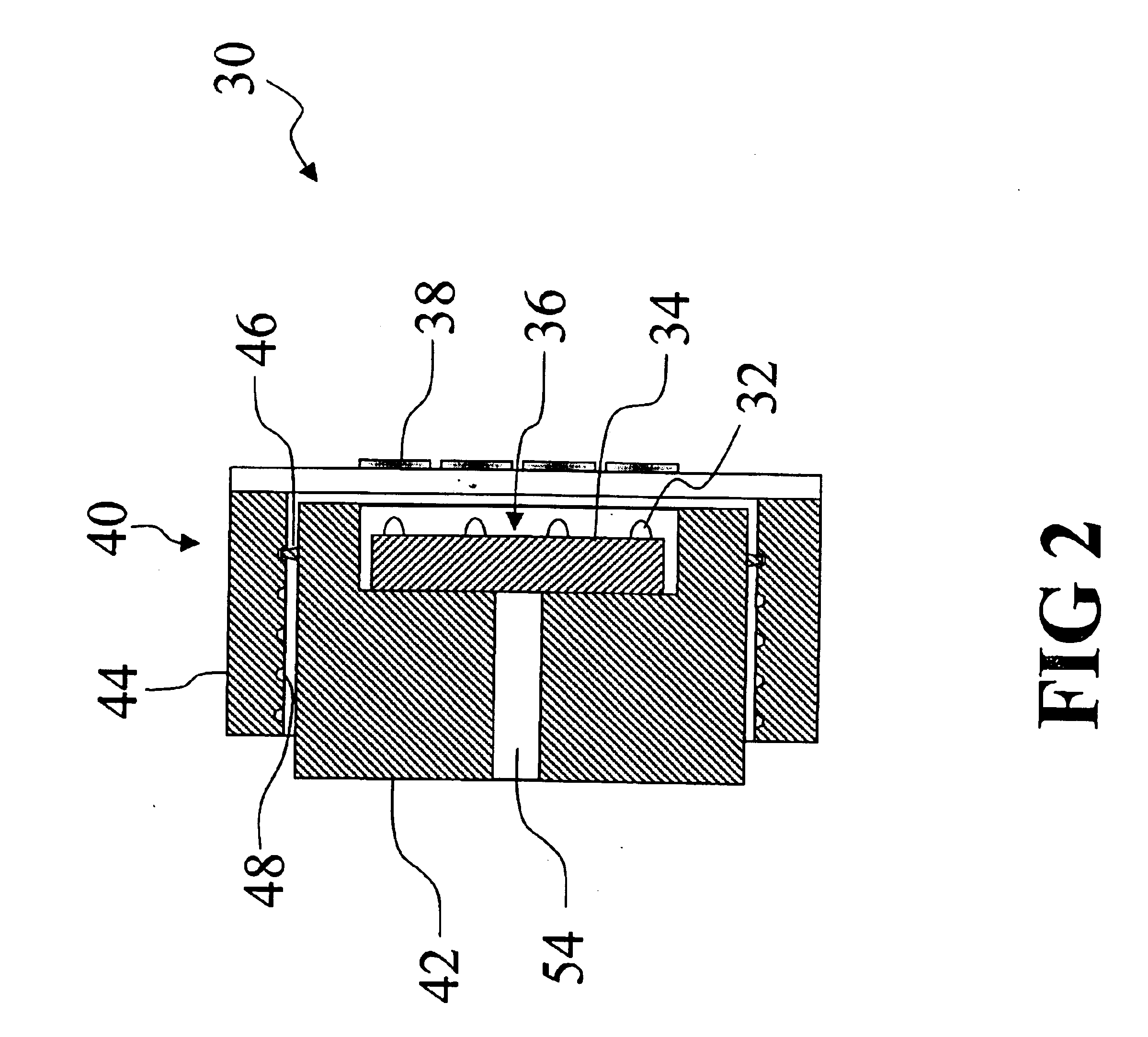
With reference to FIG. 1, a lamp that suitably practices an embodiment of the invention is described. A lamp or light source 10 includes a plurality of light emitting diodes (LED's) 12 arranged on a base or substrate 14, the combination of which forms an LED module 16. A plurality of lenses 18 are arranged in conjunction with the LED's 12, such that each LED 12 lies on the optical axis of one of the lenses 18. The lenses 18 effectuate a collimation of the light emitted by the LED's 12, so that the lamp output is a collimated or conical beam having a desired angle of divergence. Preferably, the LED's 12 are positioned closely to the lenses 18 to maximize the light captured. For this reason, the lenses 18 should be fast lenses, i.e., should have a low f number. These preferred lens optical properties are not readily obtainable using conventional lenses. Accordingly, fresnel lenses are advantageously used for the lenses 18 to provide very low f number behavior in a reasonably sized len...


PUM


Abstract

A lamp (10, 30, 80) includes an LED module (16, 36, 86) having at least one LED (12, 32, 82) arranged on a substrate (14, 34, 84). An optical system includes at least one lens (18, 38, 88) in optical communication with the LED module (16, 36, 86). A zoom apparatus (20, 40, 90) selectively adjusts the relative axial separation of the optical system and the LED module (16, 36, 86). In one embodiment (30), the zoom apparatus (40) is slidably adjustable. In a another embodiment (80), the zoom apparatus (90) is rotatably adjustable.

Description

BACKGROUND OF INVENTION1. Field of the InventionThe invention relates to the lighting arts. It is especially applicable to the packaging of light emitting diodes (LED's) to form a spot light, flashlight, or other lamp type that produces a collimated or partially collimated beam, and will be described with particular reference thereto. However, the invention will also find application in packaging of LED's, semiconductor lasers, halogen bulbs, and other light emitting elements for spot lighting, flood lighting, and other optical applications.2. Discussion of the ArtSpot light lamps emit a collimated or partially collimated beam of light (e.g., a conical beam), and are employed in room lighting, hand-held flashlights, theater spot lighting, and other applications. Examples of such lamps include the MR-series halogen spotlights which incorporate an essentially non-directional halogen light bulb arranged within a directional reflector, such as a parabolic reflector. The MR-series haloge...

Claims


Application Information

Patent Timeline
Patent Type & Authority Patents(United States)
IPC IPC(8): F21V5/00F21V14/06F21V14/00F21V14/02F21V19/00
CPCF21V5/006F21V14/065F21V14/06F21V14/02F21V14/025Y10S362/80F21V19/001F21Y2101/02F21Y2115/10F21L4/027
Inventor SOMMERS, MATHEWPETROSKI, JAMES T.
Owner GELCORE LLC (US)
Why Eureka
Try Eureka