

Connector terminal
a technology of connecting terminals and connectors, applied in the direction of cable terminations, coupling device connections, contact member manufacturing, etc., can solve the problems of insufficient strength or rigidity of the foot portion of the tab, and achieve the effect of enhancing strength and rigidity of the foot portion
- Summary
- Abstract
- Description
- Claims
- Application Information
AI Technical Summary
Benefits of technology
Problems solved by technology
Method used
Image

Examples
first embodiment
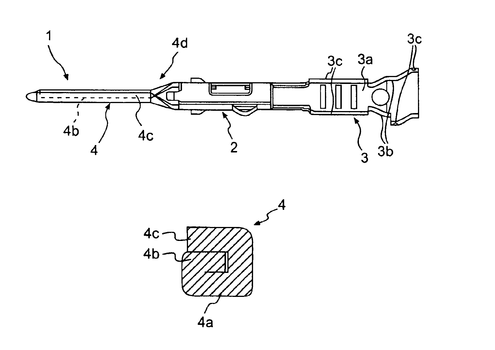
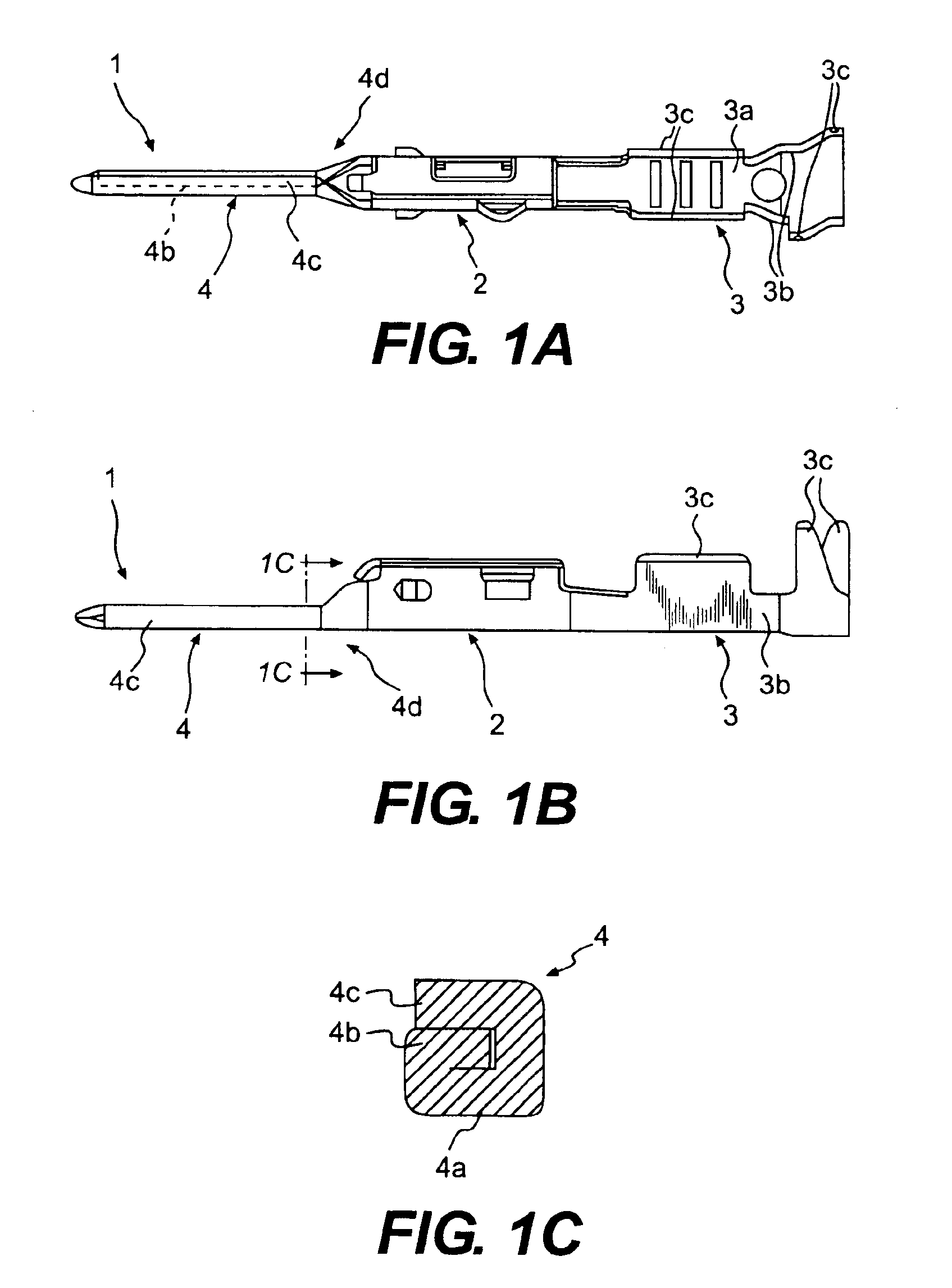
As shown in FIGS. 1A and 1B, a connector terminal 1 is formed by bending a metal plate of a predetermined shape. The connector terminal 1 is composed of a terminal base portion 2, an electric wire fixing portion 3 extending on a back end of the terminal base portion 2, and a tab 4 extending on a tip end of the terminal base portion 2 for contact with an opponent terminal. The electric wire fixing portion 3 includes a bottom face portion 3a, a pair of side plate portions 3b standing on the right and left sides of the bottom face portion 3a, and electric wire caulking portions 3c extending above the respective side plate portions 3b. Moreover, an end of an electric wire (not shown) is inserted into a space defined by the bottom face portion 3a and the pair of side plate portions 3b, and the electric wire is fastened by bending the electric wire caulking portions 3c so as to overlap the inserted electric wire.
The tab 4 includes a bottom face portion (foot base portion) 4a, a first fold...
second embodiment
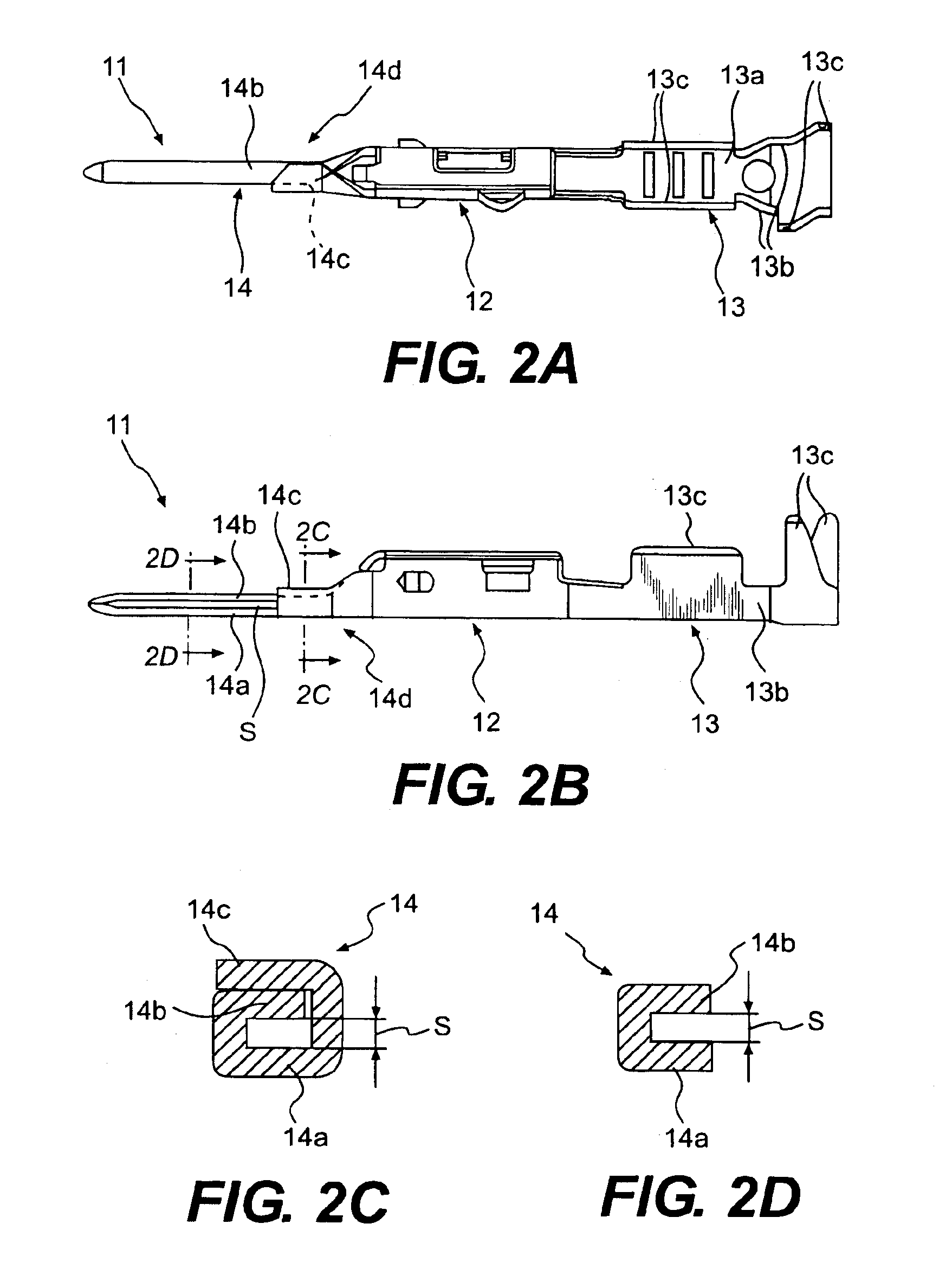
As shown in FIGS. 2A and 2B, a connector terminal 11 is formed by bending a metal plate of a predetermined shape. The connector terminal 11 is composed of a terminal base portion 12, an electric wire fixing portion 13 extending on a back end of the terminal base portion 12, and a tab 14 extending on a tip end of the terminal base portion 12 for contact with an opponent terminal. The electric wire fixing portion 13 includes a bottom face portion 13a, a pair of side plate portions 13b standing on the right and left sides of the bottom face portion 13a, and electric wire caulking portions 13c extending above the respective side plate portions 13b. Moreover, an end of an electric wire (not shown) is inserted into a space defined by the bottom face portion 13a and the pair of side plate portions 13b, and the electric wire is fastened by bending the electric wire caulking portions 13c so as to overlap the inserted electric wire.
The tab 14 includes a bottom face portion (foot base portion)...
third embodiment
As shown in FIGS. 3A and 3B, a connector terminal 21 is formed by bending a metal plate of a predetermined shape. The connector terminal 21 is composed of a terminal base portion 22, an electric wire fixing portion 23 extending on a back end of the terminal base portion 22, and a tab 24 extending on a tip end of the terminal base portion 22 for contact with an opponent terminal. The electric wire fixing portion 23 includes a bottom face portion 23a, a pair of side plate portions 23b standing on the right and left sides of the bottom face portion 23a, and electric wire caulking portions 23c extending above the respective side plate portions 23b. Moreover, an end of an electric wire (not shown) is inserted into a space defined by the bottom face portion 23a and the pair of side plate portions 23b, and the electric wire is fastened by bending the electric wire caulking portions 23c so as to overlap the inserted electric wire.
The tab 24 includes a bottom face portion (foot base portion)...
PUM
 Abstract
Description
Claims
Application Information