
Planar inverted F antenna

a technology of inverted f antennas and antennas, applied in the direction of antennas, antenna details, electrically short antennas, etc., can solve the problems of important inner spacing of products, achieve faster data processing power, improve rigidity, and compact

Inactive Publication Date: 2006-08-01
ELITEGROUP COMPUTER SYSTEMS
View PDF7 Cites 22 Cited by
  • Summary
  • Abstract
  • Description
  • Claims
  • Application Information

AI Technical Summary

Benefits of technology

The present invention is about a new type of antenna that can be used in electronic products. It uses a metal element to make the casing stronger and more rigid, and the antenna is designed to work with the metal element. The metal element helps to ground the signal and stabilize it during transmission and reception. This design makes the antenna faster and more compact, which is important for the increasing demand for faster data processing power and smaller electronic devices.

Problems solved by technology

The electronic product currently on the market is seeking faster data processing power and more compact, hence, inner spacing of the product is an important issue.

Method used


Image

  • Planar inverted F antenna
  • Planar inverted F antenna
  • Planar inverted F antenna

Examples


Embodiment Construction

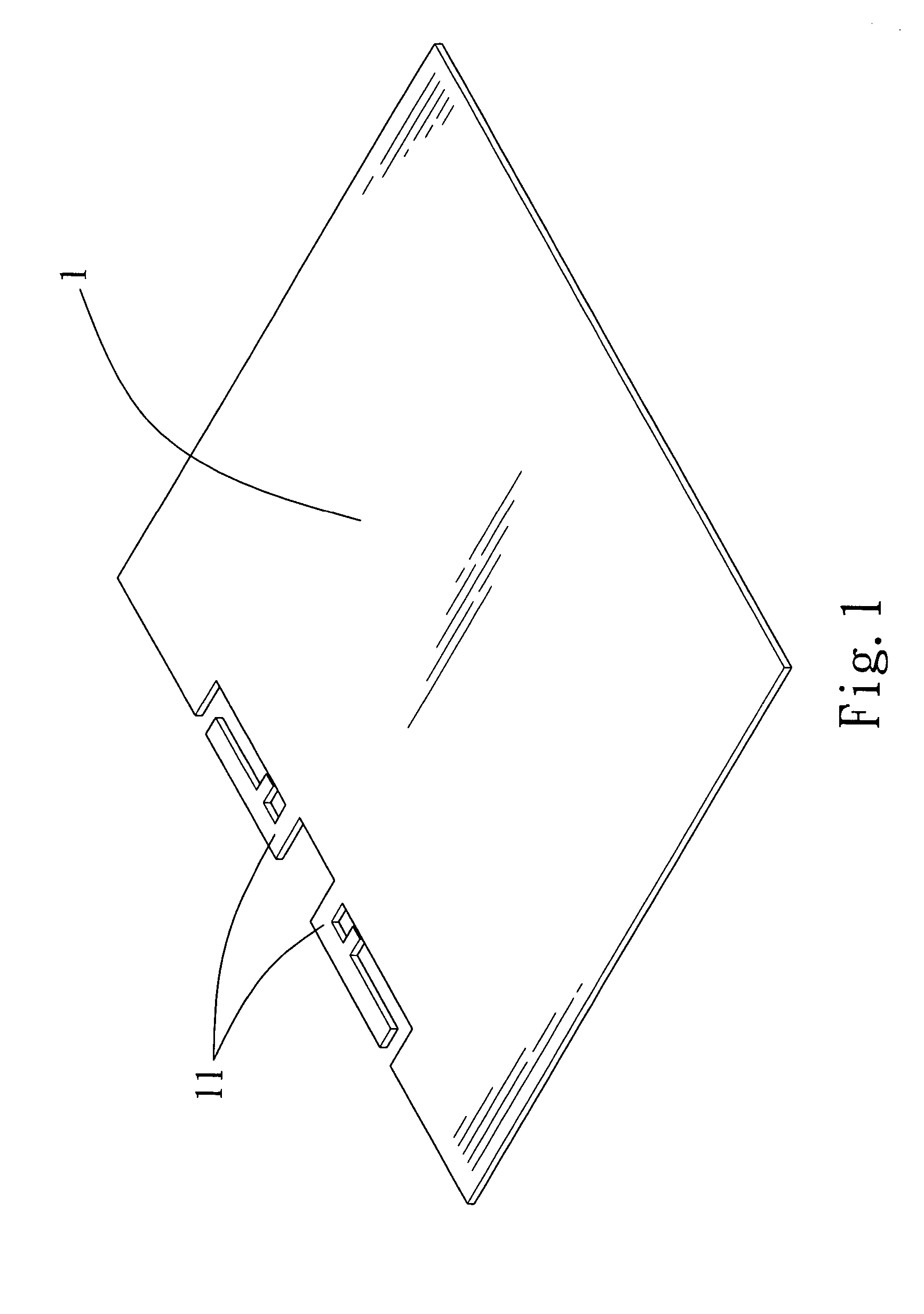
[0014]Referring to FIG. 1, which is a 3-D embodiment of the present invention. The structured PIFA comprising a conductive material with quality rigidity of metal 1, on which the antenna portion 11 was located. The antenna portion 11 formed on one side of the metal element 1 and the metal element 1 incorporate with the antenna portion 11 as a whole.

[0015]The antenna portion 11 operates at a quarter wavelength, thus resembles a PIFA. The antenna portion 11 engages with metal element 1, which acts as a broad surface for grounding. The metal element 1 stabilizes the signal while transmitting and receiving through a band of specific wavelength, diminishing the collision with other bands. Hence, the possibility of data loss and noise decreased.

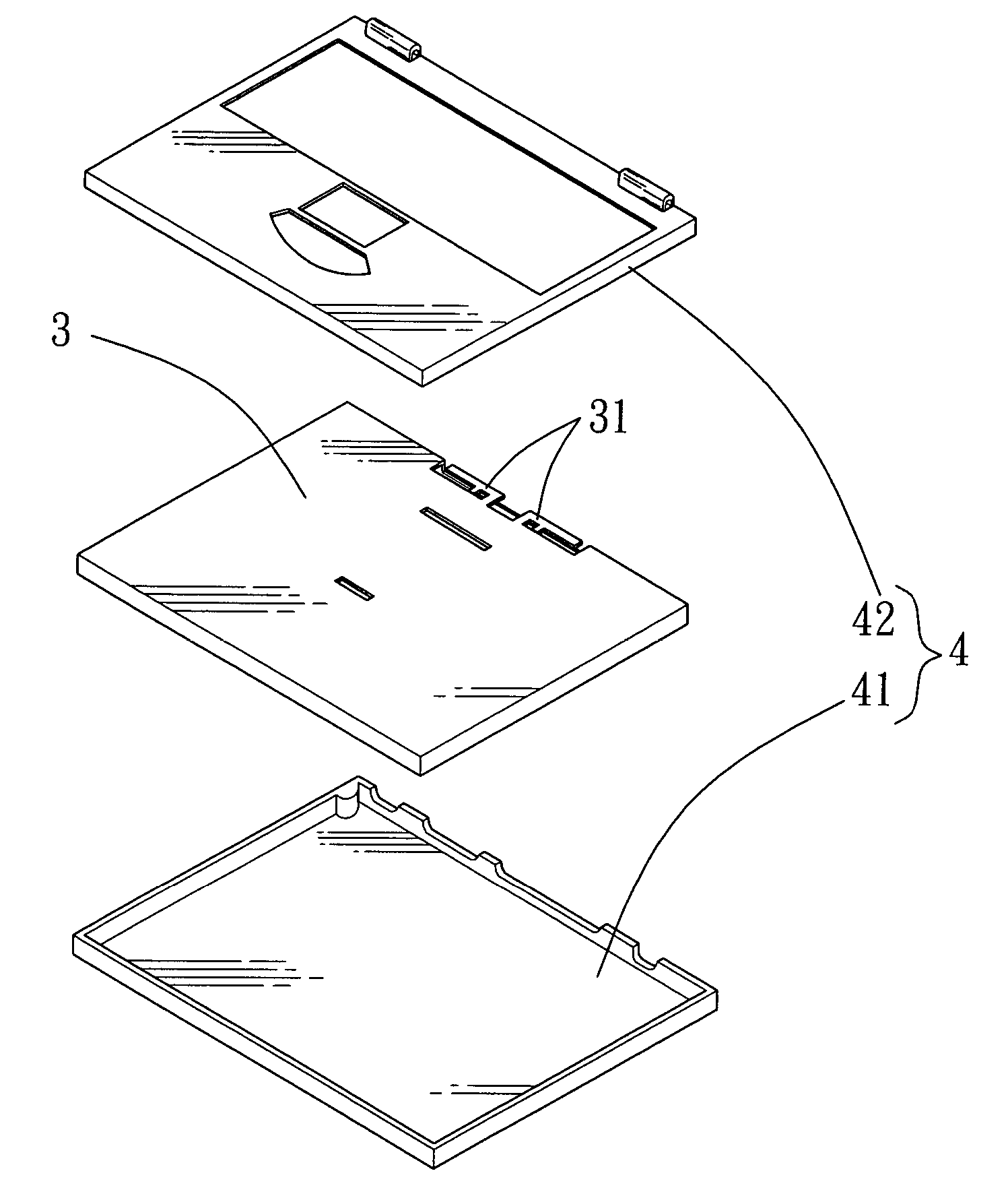
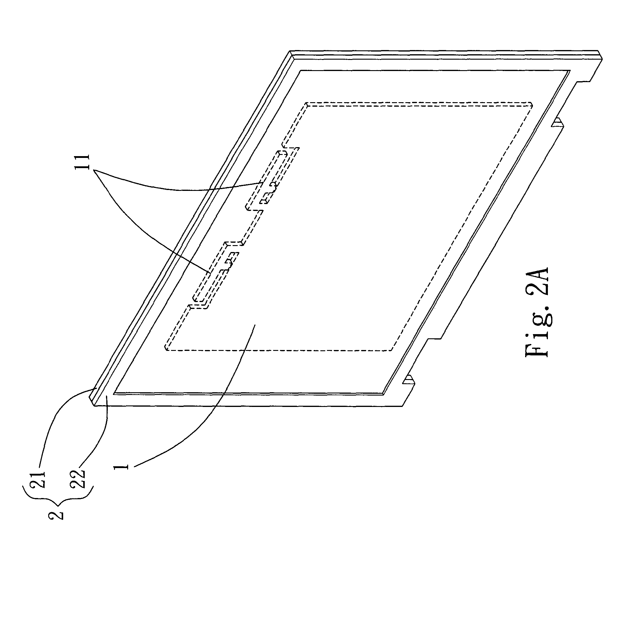
[0016]Shown in FIG. 2A, which is a first preferred embodiment of the present invention. The metal element 1 is located in a LCD monitor frame 2. The LCD monitor frame 2 comprising a front cover 21 and a rear cover 22. Firms mostly use a metal plate...


PUM


Abstract

The present invention is related to a planar inverted F antenna (PIFA), which the antenna portion is allocated on a quality conductive metal element within the electronic unit. The antenna portion and the metal element are incorporated into a single component.

Description

FIELD OF INVENTION[0001]The present invention is related to a structured planar inverted F antenna (PIFA). An antenna portion is allocated on a metal element, which is used for enhancing strength and rigidity of the casing structure. The antenna portion and the metal element in the electronic unit are incorporated into a single component. The metal element was already located in the electronic unit, thus no extra consideration needed for room reserving. Moreover, the electronic unit has electric conduction, which is capable of grounding the antenna portion. The area of the electronic unit is vast, therefore enhancing grounding, performance, and stability.BACKGROUND OF THE INVENTION / PRIOR ART[0002]With wireless communication technology maturing, wireless communication product is becoming an indispensable communication tools nowadays. With wireless local area network (WLAN) catching on with LAN, firms are adapting wireless technology on PC peripherals, at the same time applying on hom...

Claims


Application Information

Patent Timeline
Patent Type & Authority Patents(United States)
IPC IPC(8): H01Q1/24H01Q9/04
CPCH01Q9/0421H01Q1/243
Inventor CHEN, JUN-CHIALIN, HSIANG-JUI
Owner ELITEGROUP COMPUTER SYSTEMS
Learn More