Composite electromechanical machines with controller

a technology of electromechanical machines and controllers, applied in the direction of dynamo-electric converter control, motor/generator/converter stopper, multiple dynamo-motor starters, etc., to achieve the effect of reducing power, high power, and speeding up the reduction of power or speed

Inactive Publication Date: 2010-07-08
YOSHYAMA EMIKO MRS
View PDF11 Cites 9 Cited by
  • Summary
  • Abstract
  • Description
  • Claims
  • Application Information

AI Technical Summary

Benefits of technology

[0008]In an aspect, the present composite electromechanical machine comprises at least two rotor / stator pairs integrated together. In an aspect, the two stators from the two rotor / stator pairs form a double-sided stator having an inner stator side and an outer stator side. The composite double-sided stator can replace two separate inner stator and outer stator in coupling with an inner rotor and an outer rotor, respectively. In an aspect, the two rotors from the two rotor / stator pairs form a double-sided rotor having an inner rotor side and an outer rotor side. The composite double-sided rotor can replace two separate inner rotor and outer rotor in coupling with an inner stator and an outer stator, respectively. The stator and the rotors can comprise either a permanent magnet or a winding to generate a magnetic field. If the rotors comprise winding, a brush mechanism can be included to accommodate the winding. The composite electromechanical machine can be a brushless machine with the rotor comprising of at least one permanent magnet, and the double-sided stator comprising stator winding(s). The composite electromechanical machine can be a brush machine with the rotor (inner rotor, outer rotor or both rotors) comprising a winding, and the double-sided stator comprising of at least one permanent magnet. The composite electromechanical machine further comprises a controller coupled to the rotor / stator pairs to configure at least a winding of the rotor / stator pairs. Configuring a winding can configure or change the functionality or the characteristics of the rotor / stator pairs.
[0009]In an embodiment, configuring or changing the functionality of a rotor / stator pair includes making the rotor / stator pair become either a nonoperation part, a motor or a generator. For example, changing the functionality of a rotor / stator pair can include changing a motor configuration to a generator configuration, and vice versa. The controller can change the function of the composite electromechanical machine to accommodate different situations. For example, a composite electromechanical machine can comprise two rotor / stator pairs. For high motor power, the controller can configure the two rotor / stator pairs to be motor, combining their power. For reducing power, the controller can configure one rotor / stator pair to be nonoperation, such as no power or a small power to offset the magnetic braking is supplied to the rotor, the stator, or rotor / stator pair, leaving one rotor / stator pair to carry the load. If the two motor / stator pairs have different power levels, there can be two levels of power outputs, a low power with the stronger rotor / stator pair becoming nonoperation, and a high power with the weaker rotor / stator pair nonoperation. For a faster reduction of power or speed, the controller can configure one rotor / stator pair to be a generator, essentially providing a braking force on the remaining motor. This configuration can conserve energy, storing the braking power of the motor into electrical power of the generator. Similarly, if the two motor / stator pairs have different power levels, there can be two levels of braking power, a higher braking power with the high power rotor / stator pair nonoperation, and a lower braking power with the low power rotor / stator pair nonoperation. Additionally, anyone or a combination thereof can reverse the rotation of the motor for even stronger braking and coming to a complete stop.

Problems solved by technology

However, this classification is not a rigid distinction, especially with advances in electronic control, e.g., moving the commutator out of the motor shell.

Method used


Image

  • Composite electromechanical machines with controller
  • Composite electromechanical machines with controller
  • Composite electromechanical machines with controller

Examples


Embodiment Construction

[0025]Embodiments of the invention include a composite motor or generator which comprises multiple rotor / stator pairs that are configured as a double-sided stator and / or double-sided rotor and a controller for configuring at least a winding of a rotor / stator pair or for configuring or changing the functionality or characteristics of the rotor / stator pairs.

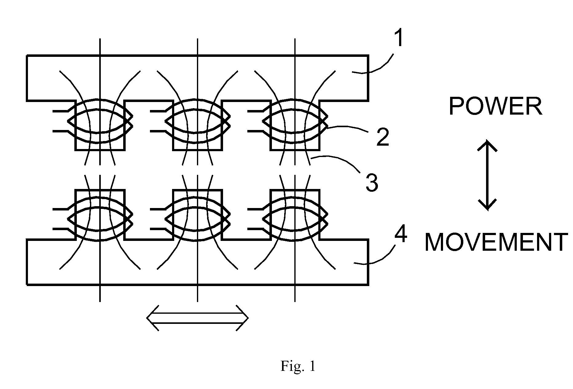
[0026]FIG. 1 illustrates the interaction of magnetic field(s) in a motor or generator. A power can be applied to a magnetic plane 1, for example, through the windings 2, to generate a magnetic field 3. Interaction of the magnetic field 3 with another magnetic plane 4 can provide a movement for this magnetic plane 4. Conversely, movement of the magnetic plane 4 can generate power within the windings 2 of the magnetic plane 1. In this configuration, certain magnetic field is directed away from the interaction, and thus does not contribute to the power transfer

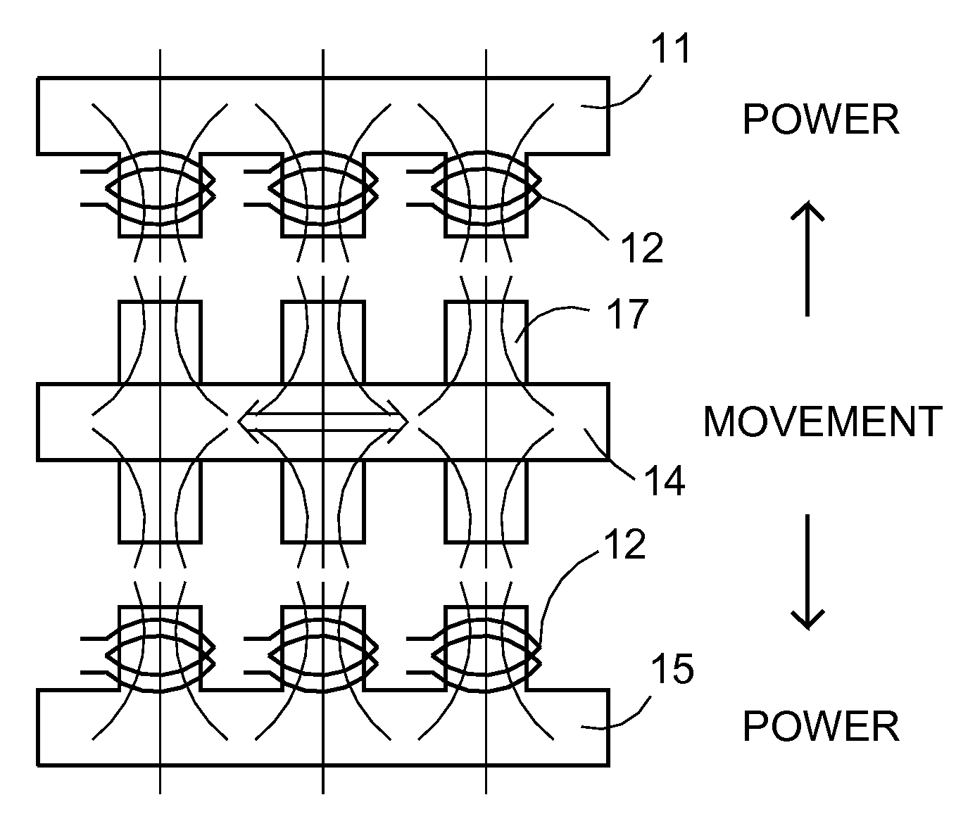
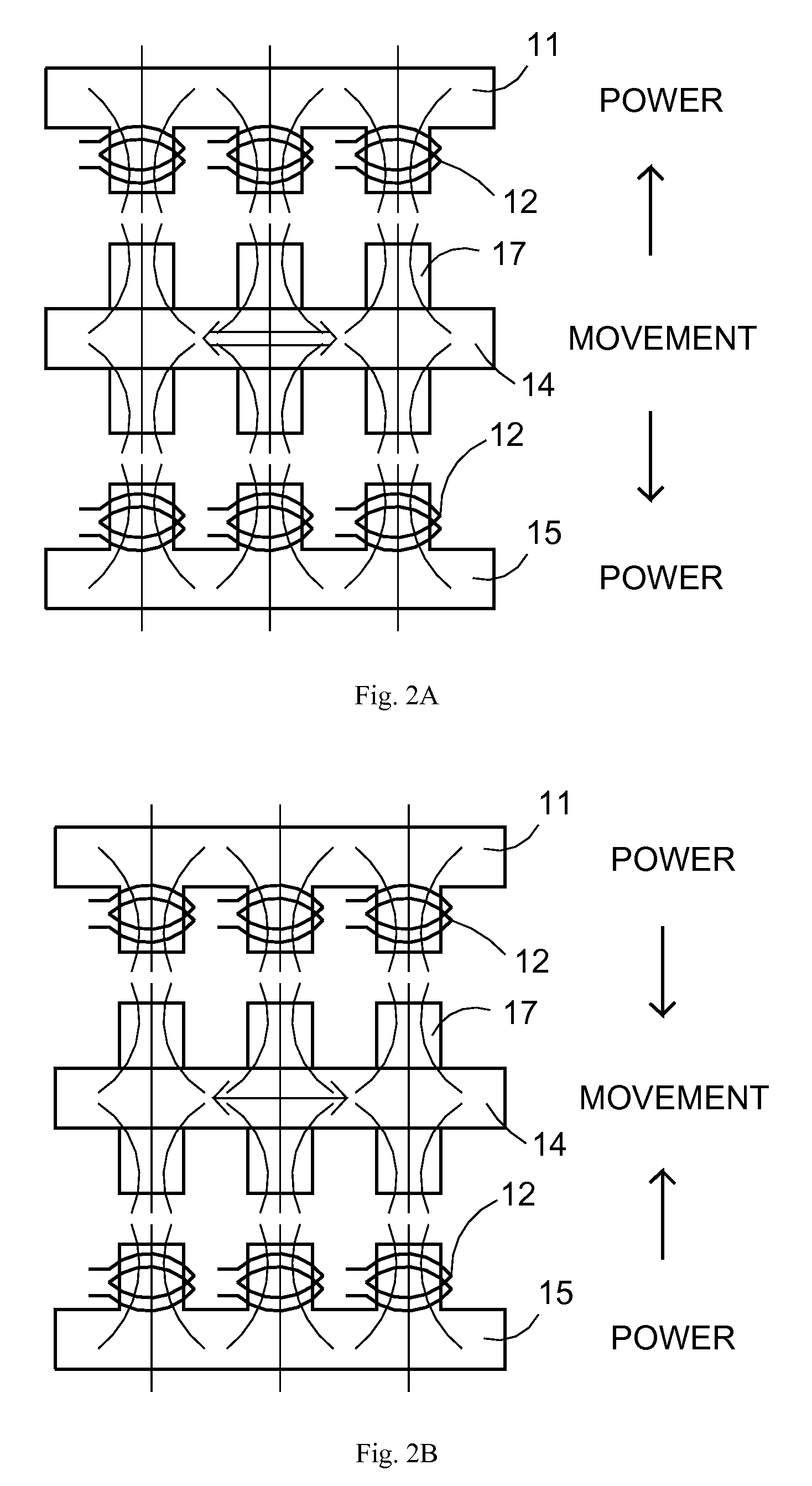
[0027]FIG. 2A illustrates a schematic for a generator using a double-sided ...


PUM


Abstract

Embodiments of the present invention include a composite electromechanical machine which can operate as a motor, a generator (including dynamo or alternator), or any combination thereof. In an aspect, the present composite electromechanical machine comprises at least a double-sided magnetic plane (e.g., rotor or stator) to form two rotor/stator pairs, together with a controller to configure the multiple rotor/stator pairs. The controller can configure or convert the multiple rotor/stator pairs into motors, generators, or nonoperation, and also can change the windings characteristics of the magnetic planes. The controller can add new functionality and characteristics to the present composite electromechanical machine. Other embodiments can also be included.

Description

[0001]The present invention is related to application Ser. No. 12 / 210,169, filing date Sep. 12, 2008, entitled “Composite electromechanical machines with gear mechanism”, and to application Ser. No. 12 / 210,171, filing date Sep. 12, 2008, entitled “Composite electromechanical machines with uniform magnets”, hereby incorporated by reference. The present invention relates generally to electromechanical machines, such as motor, generator, dynamo, or alternators, and particularly to composite electromechanical machines.BACKGROUND [0002]Electromechanical machines such as alternator(s), motor(s), dynamo(s), and generator(s) can convert energy between mechanical energy and electrical energy. For example, an electric motor uses electrical energy to produce mechanical energy, and a generator or dynamo uses mechanical energy to produce electrical energy. In general, an electromechanical machine can operate as a motor or as a generator, depending on the applied input energy. The major differenc...

Claims


Application Information

Patent Timeline
Patent Type & Authority Applications(United States)
IPC IPC(8): H02P6/00H02K21/12
CPCH02K9/06H02K9/22H02K21/12H02K9/227
Inventor QUERE, ERIC STEPHANE
Owner YOSHYAMA EMIKO MRS
Why Eureka
Try Eureka